Paint booth (part 2): Venting
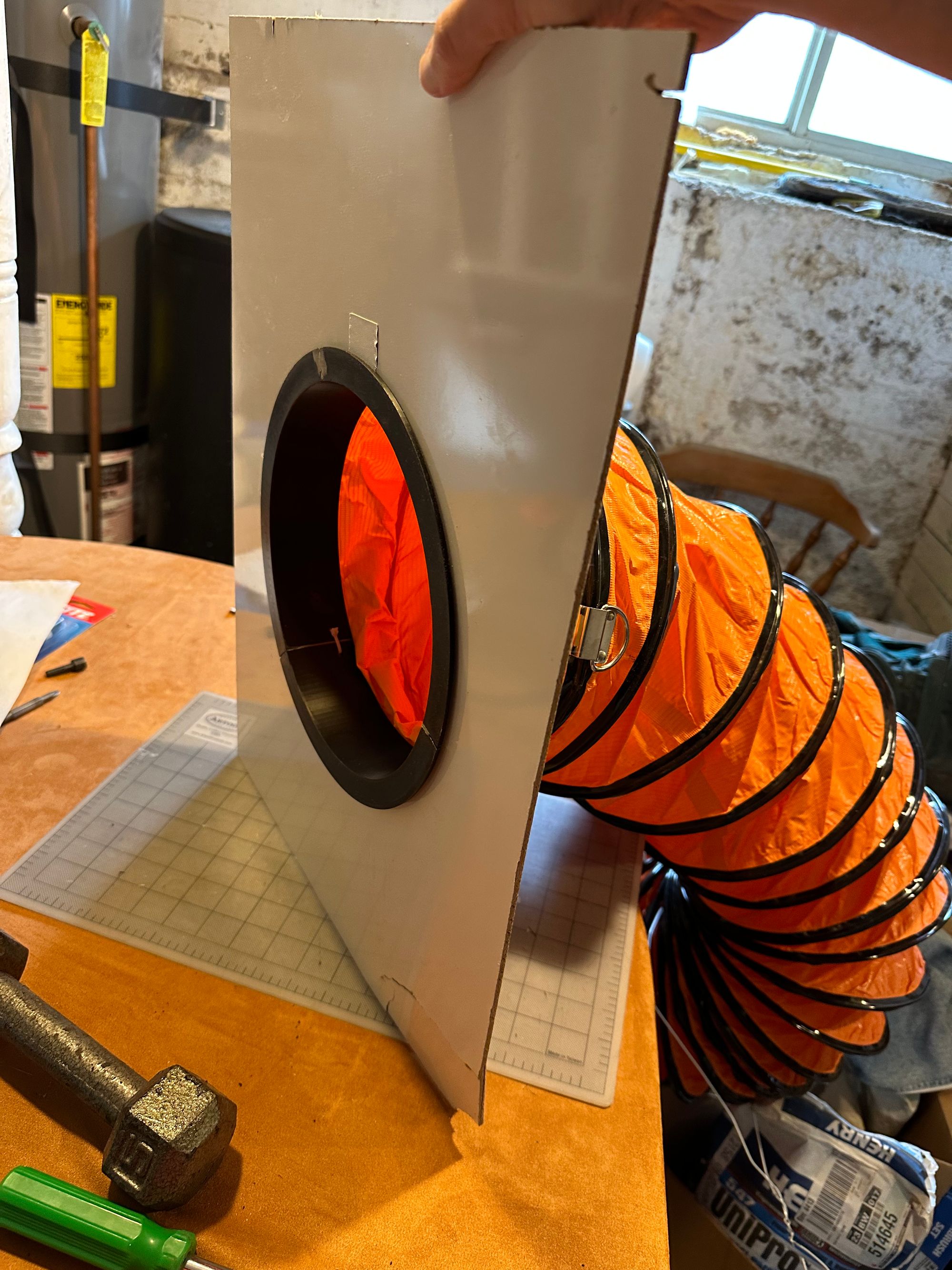
When we left off last, I’d finished the structure of my collapsible paint booth, but I was venting it out the window with a precarious, clearly-temporary rolled posterboard vent. It was flimsy, not waterproof, and honestly quite a pain to use.
A tool that’s frustrating to use is a tool that I will tend to avoid using, so getting to a more permanent and user-friendly solution for venting became top priority.
I was looking for something basically like a dryer vent; a bit of ducting to connect the hose to and a hood to keep rainwater out of the opening. However, my tenuous grasp of fluid dynamics suggested that significantly narrowing the diameter of my vent would reduce its effectiveness, so I was looking for quite a large dryer vent; 10-inch diameter. Turns out that such things are a bit on the pricey side. I thought, I have a 3d printer, I can just fabricate what I need. If I’d realized then the effort I was about to undertake, maybe I would have reconsidered; but then, pragmatism is not always the reason for doing things oneself.
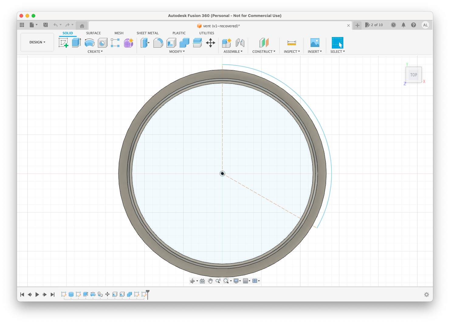
First thing was to select a material. Up til now, I’d been printing with PLA. However, the internet suggested that it might do poorly in heat and sunlight. PETG and ASA were recommended, but are a bit more expensive, and given that my vent wouldn’t be exposed to the elements all the time—just as needed—ABS felt like an acceptable cost-saving compromise.
I’d read that ABS could be difficult to work with, but I’d had good luck with 3d printing so far; how hard could it be?
Now, to model the pieces I needed. I figured I’d make a duct ring, and then a hood that could slide onto it, but could be disassembled again in the future.
I’d learned Cinema4D (C4D) in college, and past prints I had made were either aesthetic pieces that I’d modeled or models that I’d downloaded from the internet. Given that precision was more important for this kind of functional print, I figured it was time to start learning a more specialized CAD tool like Autodesk Fusion 360.
Reader, I hated it.
Really my own fault, because despite hearing that it was a difficult program to use, I figured I could get by; I had prior experience with 3d modeling, and I have been teaching myself software and figuring out interfaces pretty much my whole life. Fusion 360 was much less comprehensible than I’d expected, and I clearly overestimated my ability to figure it out on my own. Noticing a theme here?
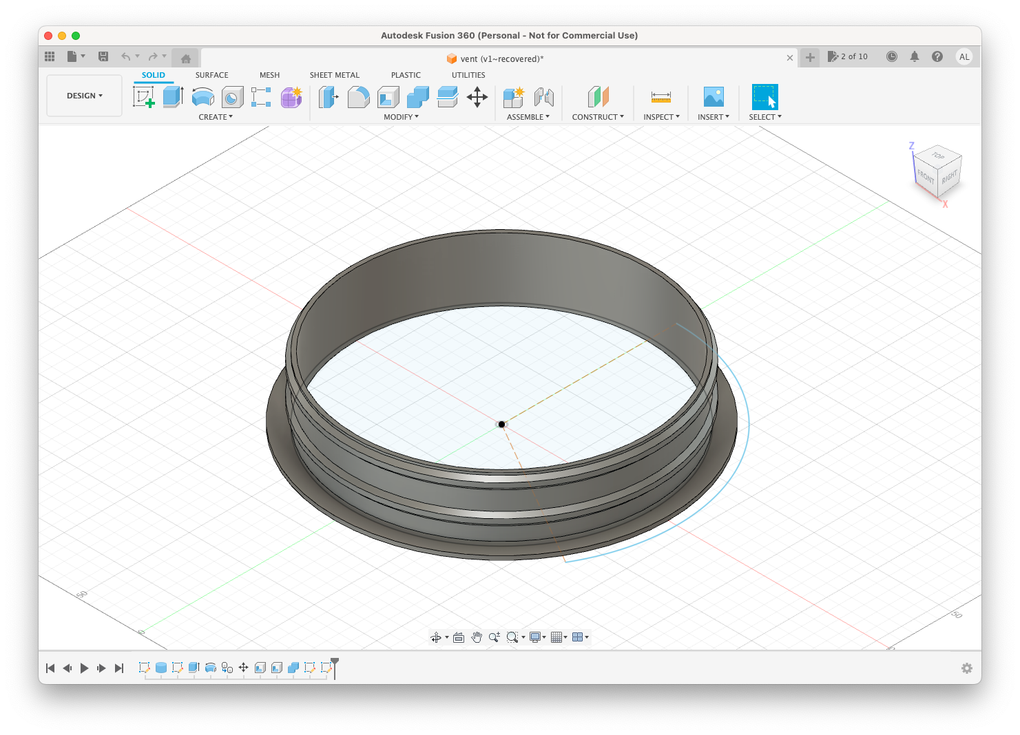
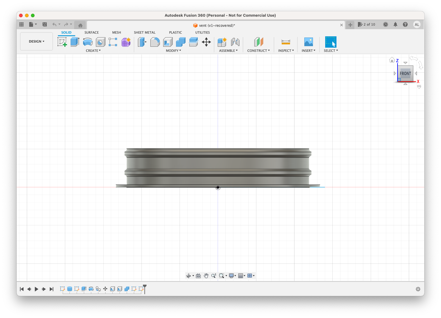
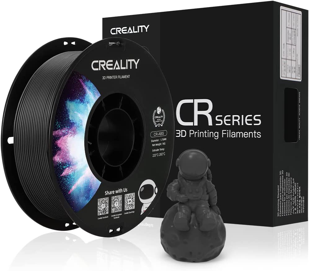
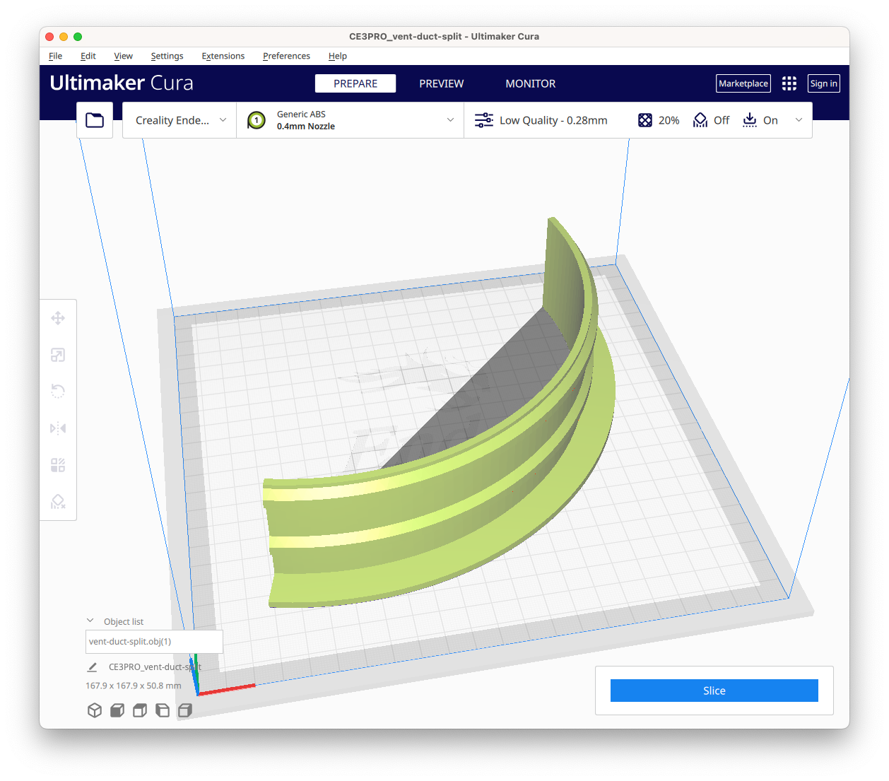
After fumbling my way through for several painful hours, I finally had a model for my duct ring. I was also frustrated enough by the effort it had taken to achieve this simple part that I decided to pull the ripcord on Fusion 360 and fall back to C4D. Other than the slot that the duct ring would fit into, precision was not as important on the hood, so I figured I’d get away with it. Before that, however, I wanted to get the ring printing, which is when I hit another snag.
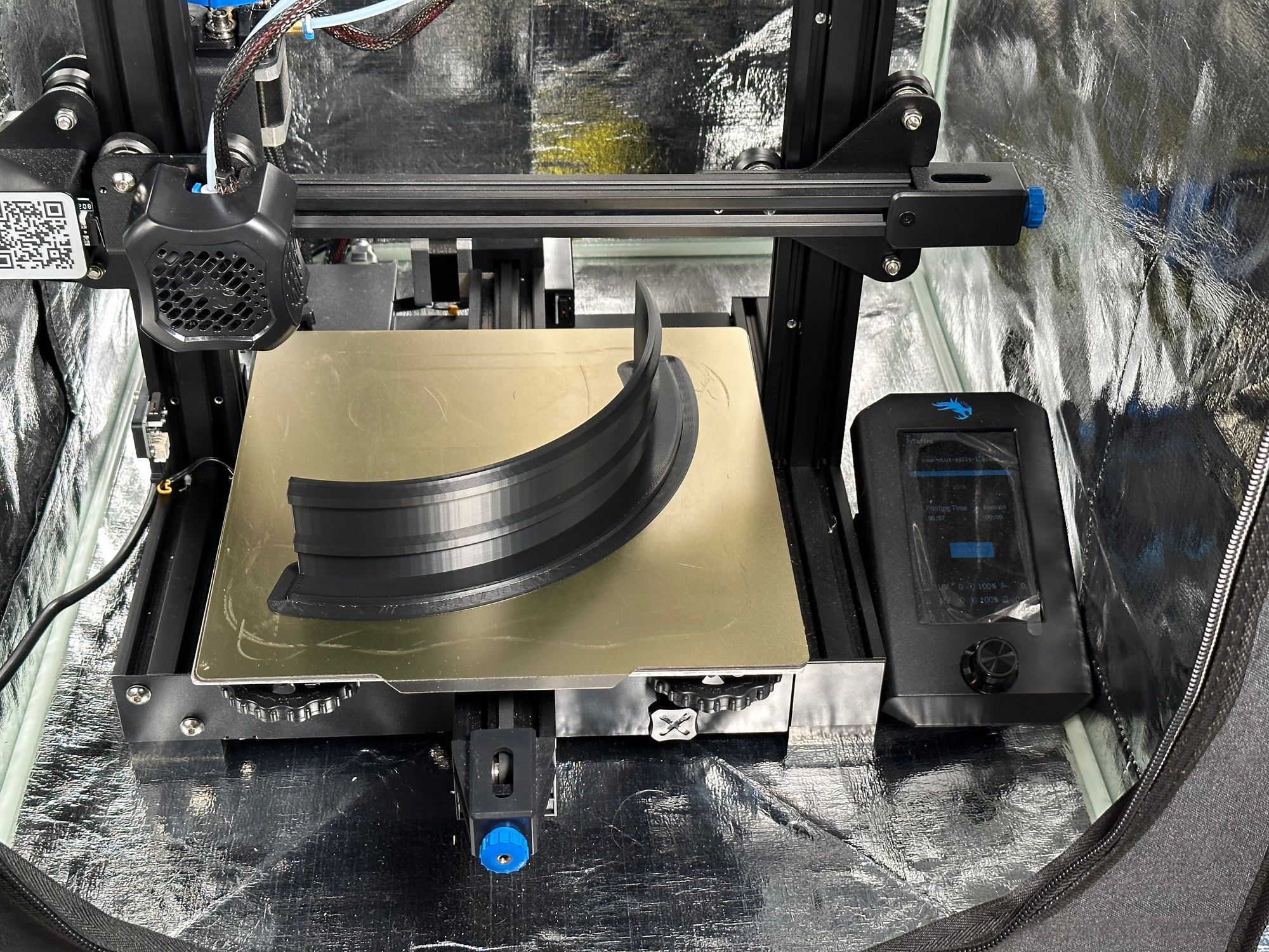
I had misremembered the printing area of my Ender 3 v2, so the ring could not be printed as a single piece. I was not touching Fusion 360 at this point, so I just imported the .obj into C4D and split it into thirds.
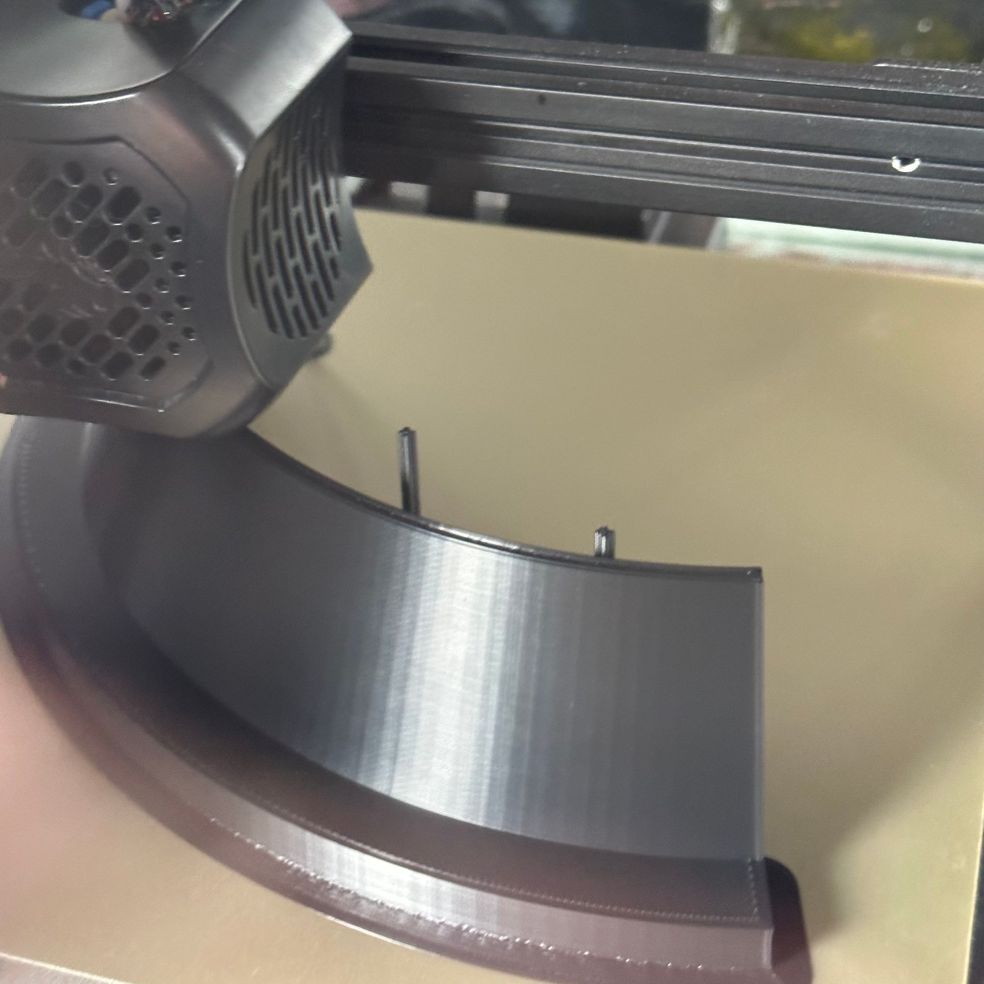
From there, I started printing, and... disaster.
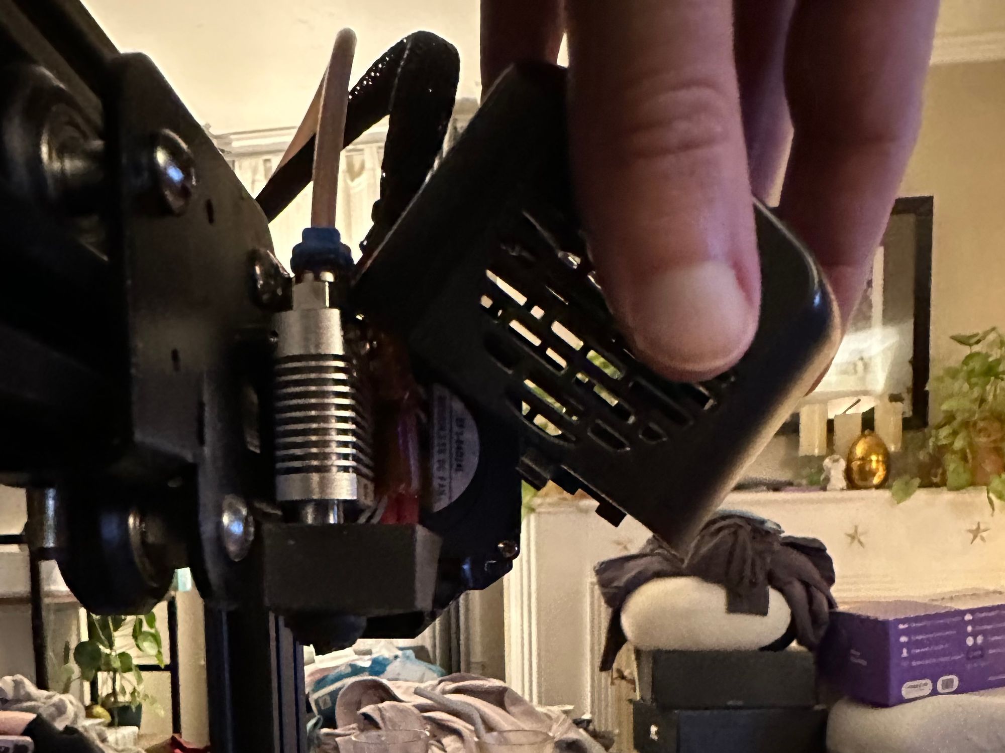
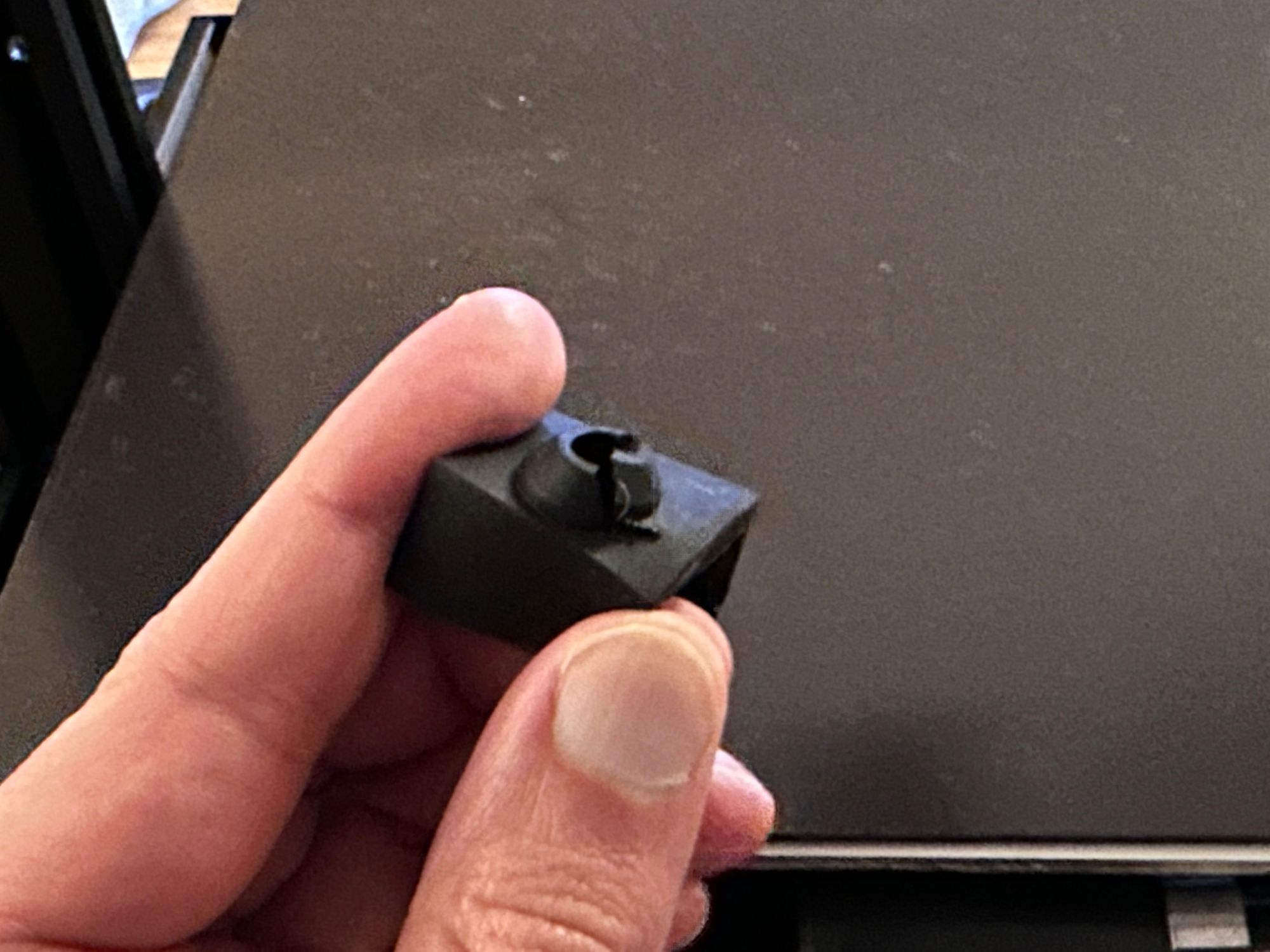
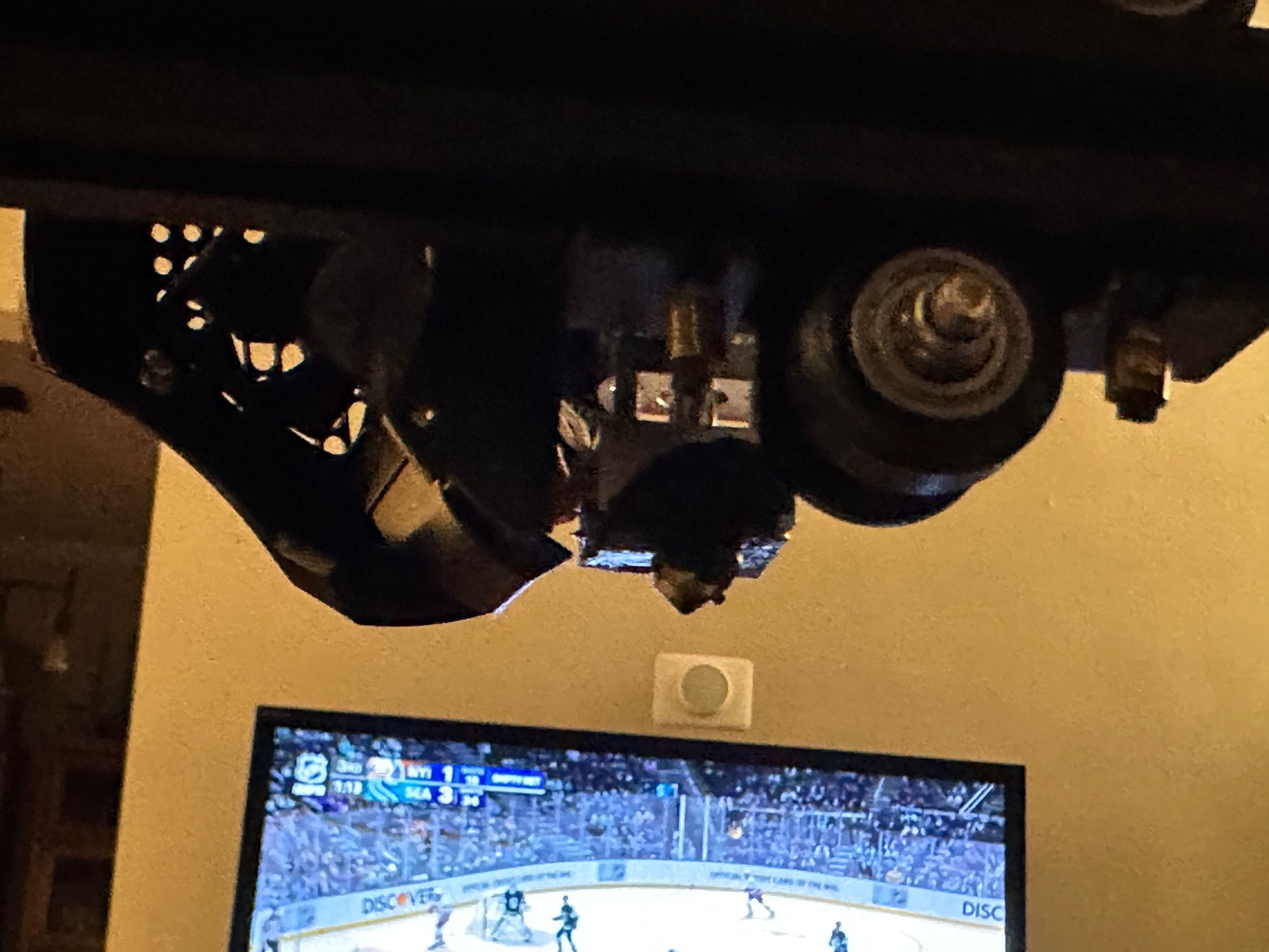
Well, a very minor disaster. The print warped after a few layers, coming away from the build plate, snagged and ripped the silicone sock that surrounds the extruder, and the printer kept going, globbing up material around the extruder. Having seen photos of extruder disasters, I worried that I’d have to replace some significant parts, but in the end, after a little light disassembly, I determined the plastic hadn’t gotten into any delicate parts; I got the heating element back up to temperature, and was able to pull the plastic off entirely with tweezers. Then I just had to order some replacement silicone socks, and I was back in business.
Reading more about ABS printing online, I began eliminating the various common issues that could lead to improper build plate adhesion. I’ve been using a flexible PEI build plate, which should be very good for adhesion. However, going over all the details, I came to a conclusion—the ABS temperature presents in my slicer software, Ultimaker Cura, are garbage. In general, I’ve been quite happy with Cura, but the preset was heating the plate to 80°C. The internet recommended somewhere between 100°C and 120°C for proper adhesion. With my temperatures adjusted (I settled on 110°C as a compromise, which also happens to be the highest the bed temperature will go), and with a brim added to increase the adhesion surface area, I was ready to go once more.
Success! Well, until I tried to get the piece off the build plate.
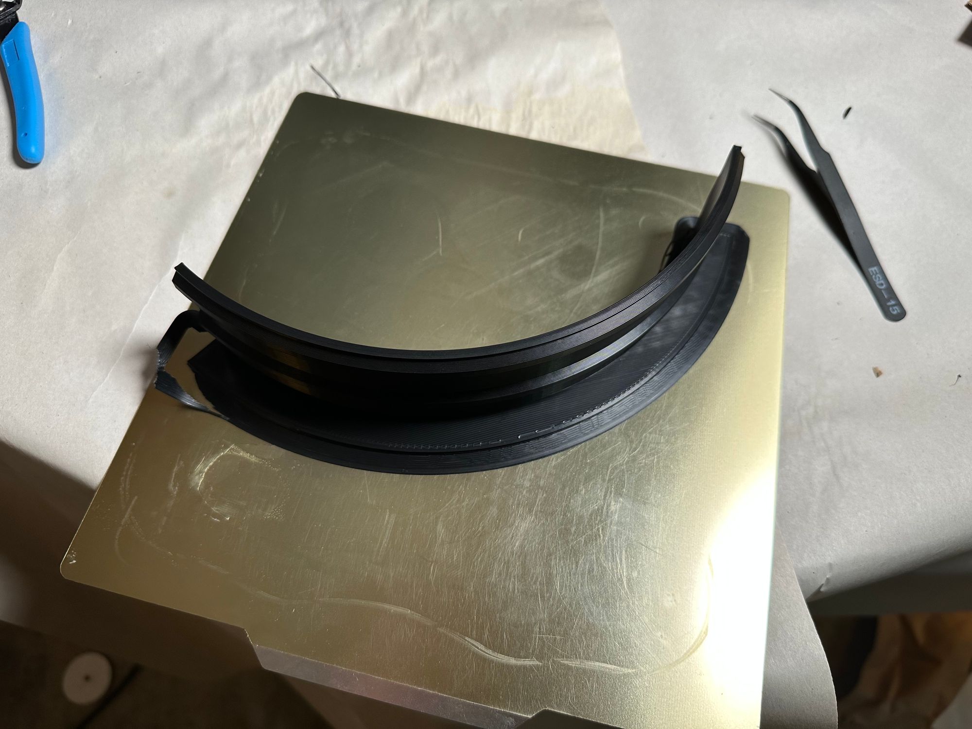
It was on there good. I am used to being able to just pop my PLA parts off the flexible plate, but this was not budging. I tried to pry it off with a scraper, and ended up ripping the PEI coating off the metal plate rather than releasing the ABS from it. Oh well, the build plate is a “consumable” anyway. I finally tried warming the plate back up, and despite being quite hot to the touch (gloves recommended), the print finally came right off.
So, I ordered another PEI build plate, and a few days later I was able to print the other two pieces without incident.
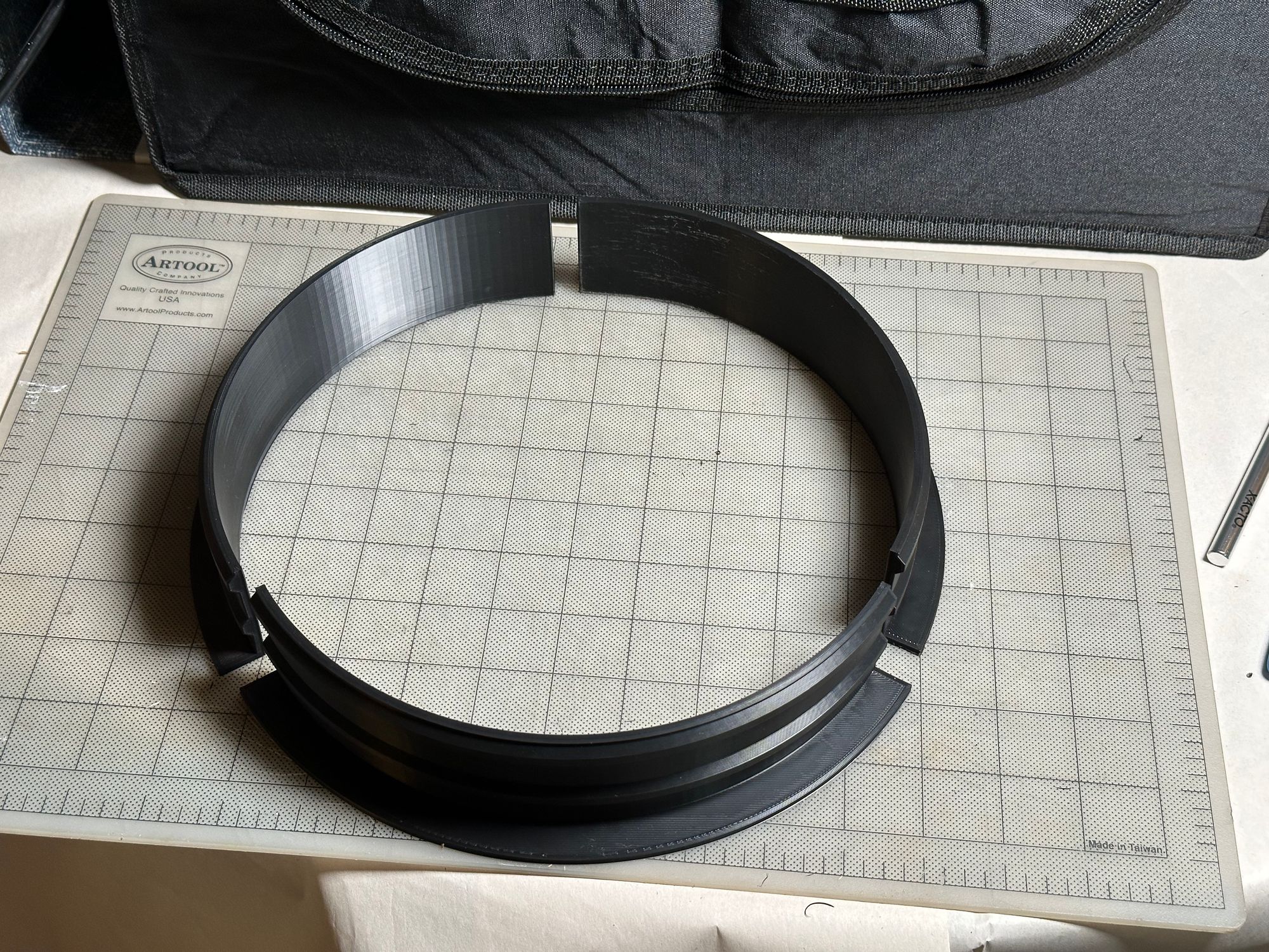
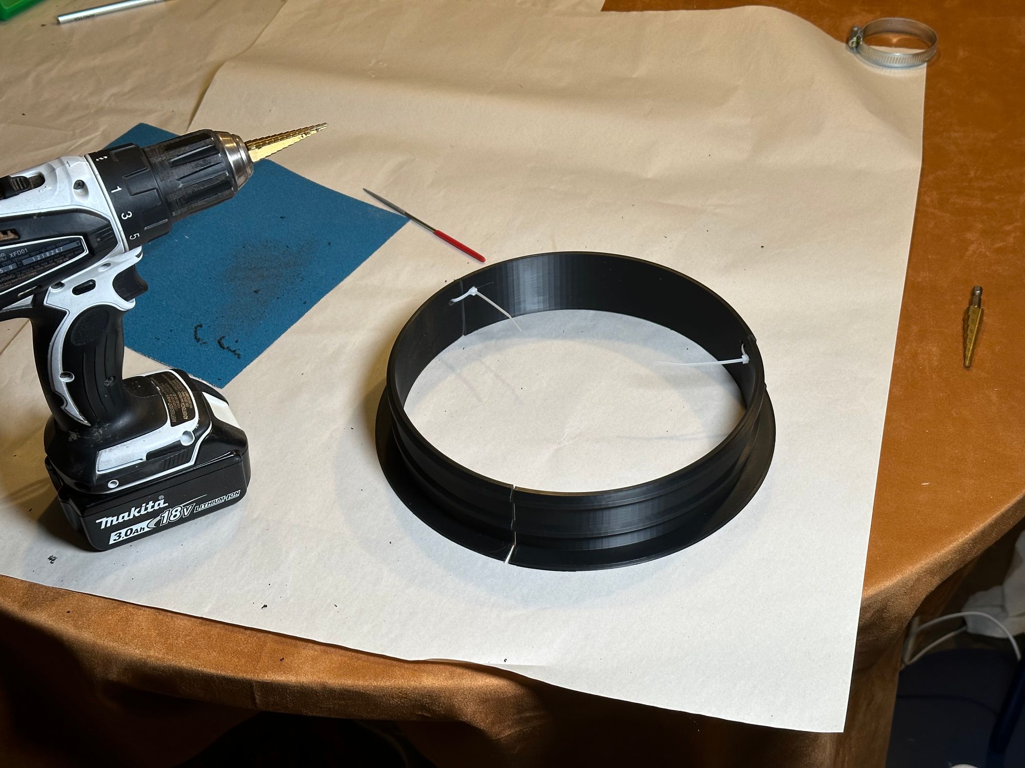
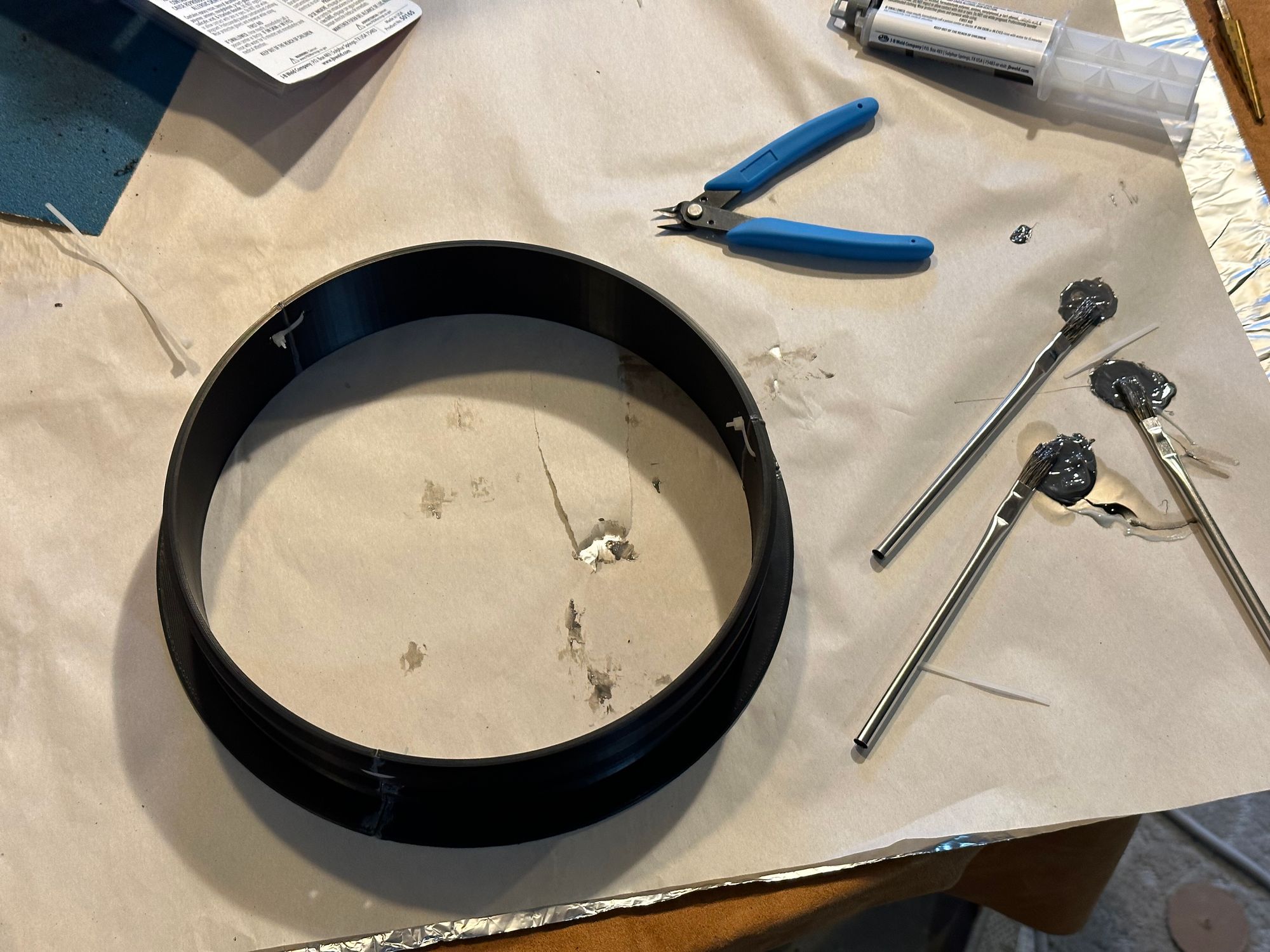
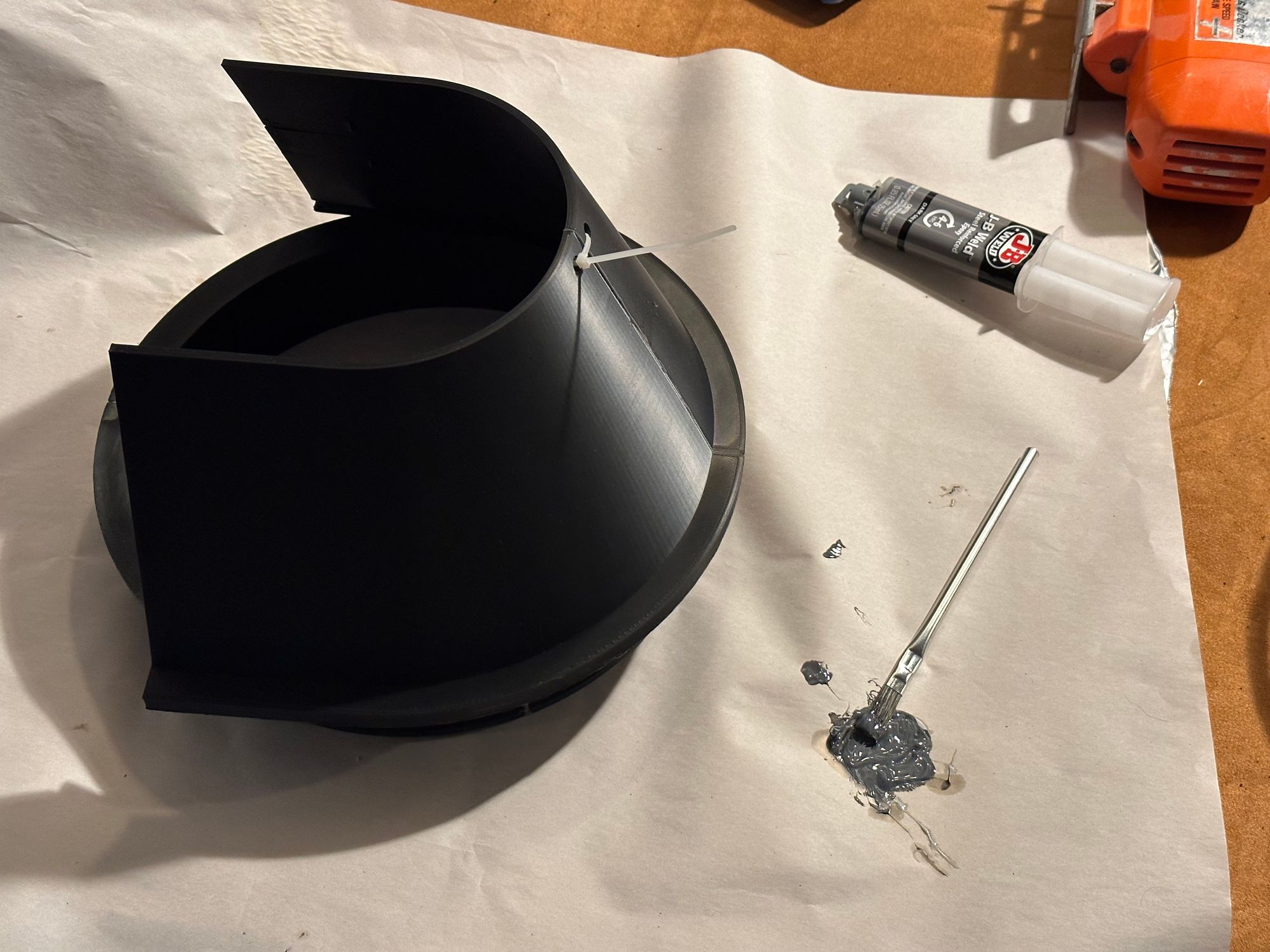
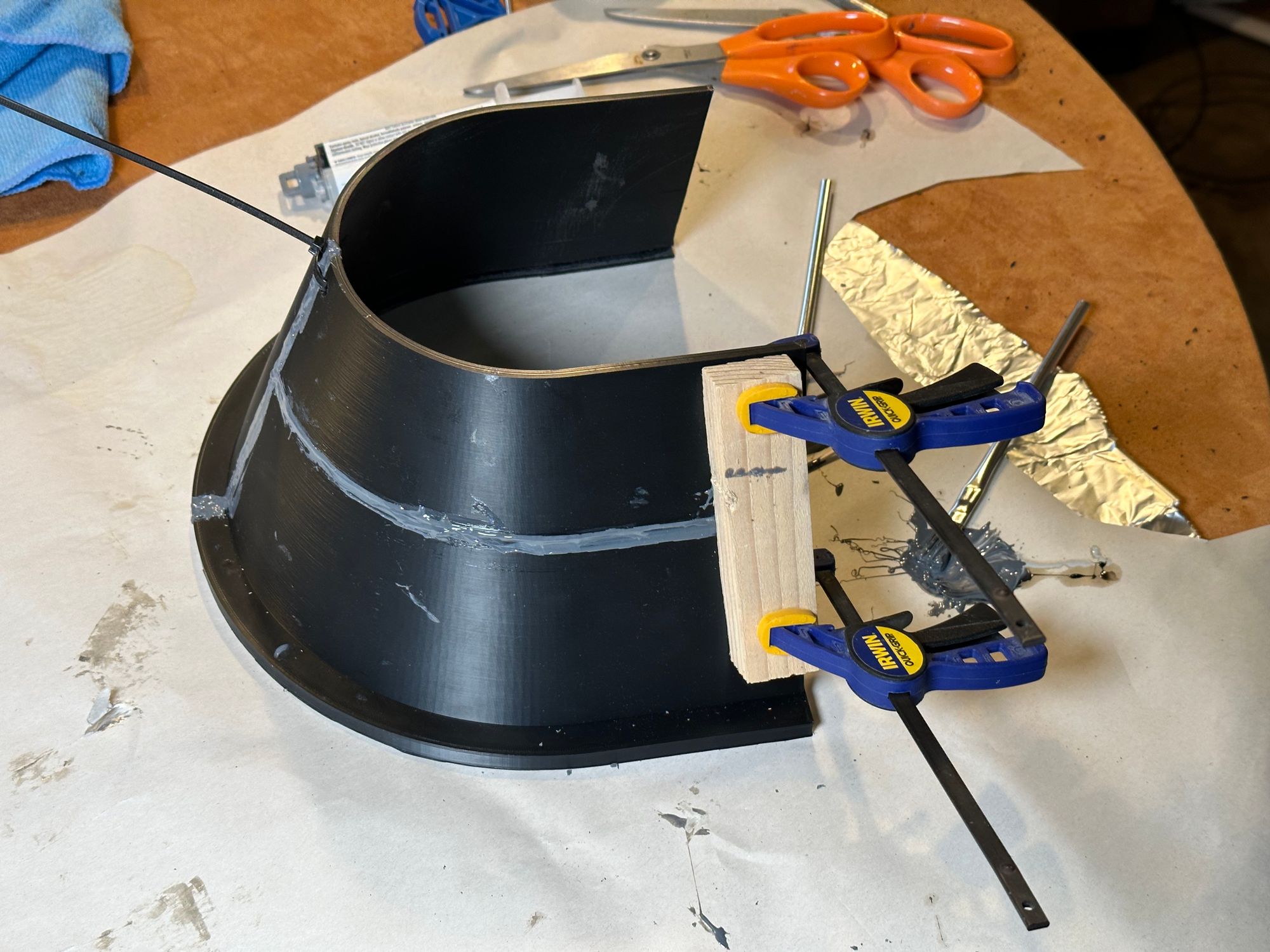
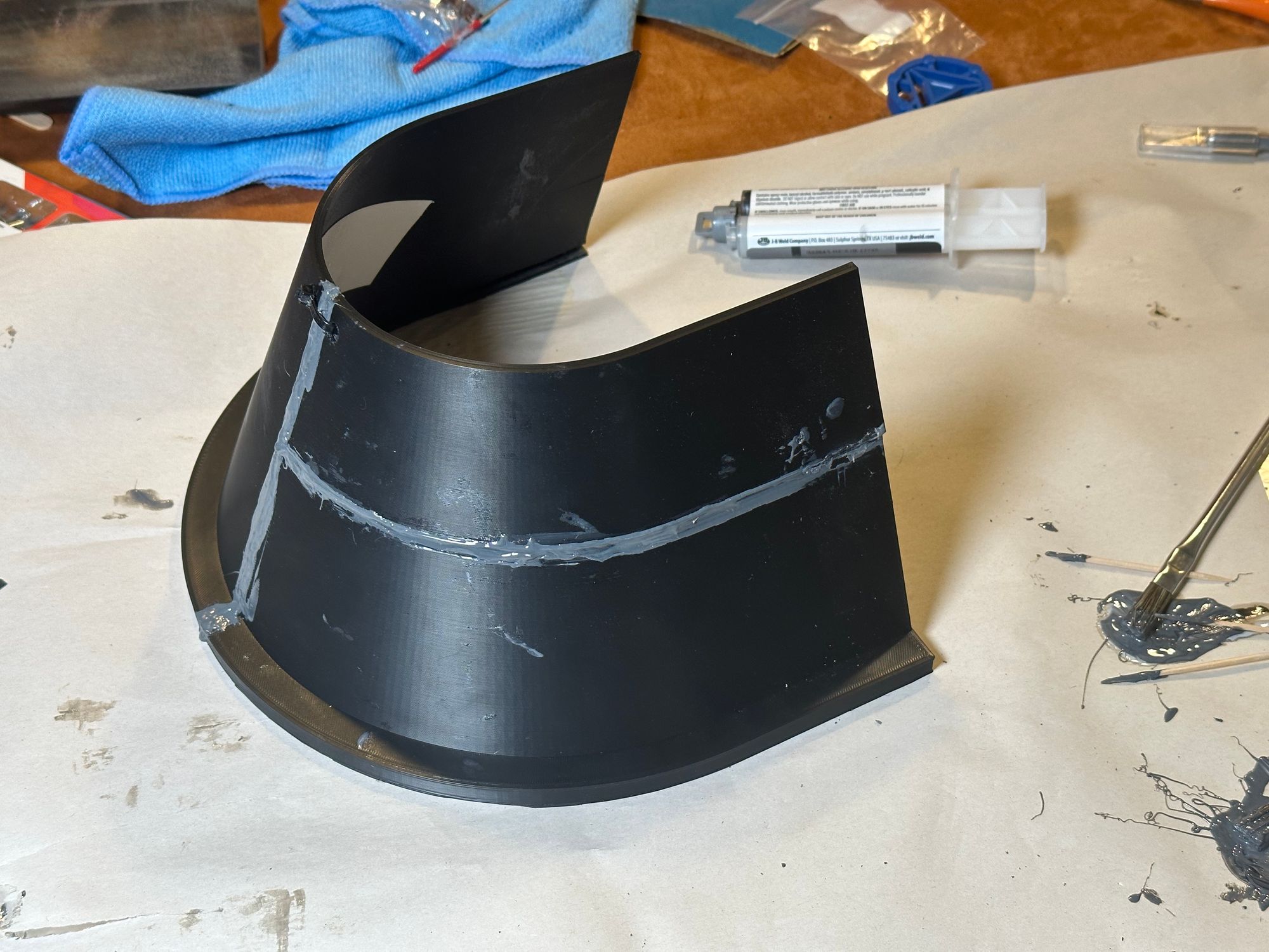
After some reading about different glues for ABS, I settled on epoxy. I’d originally thought that I could clamp these pieces together while the epoxy cured, but it turns out clamping semicircles together is really challenging. I eventually chose instead to drill some small holes and zip tie the pieces together to maintain their shape. For each joint, I cut the zip tie with nippers, applied epoxy with a brush, and then re- zip tied it back together. Once all three joints were epoxied, I figured there was no reason not to leave the zip ties, so I just trimmed the tails and left them for extra strength.
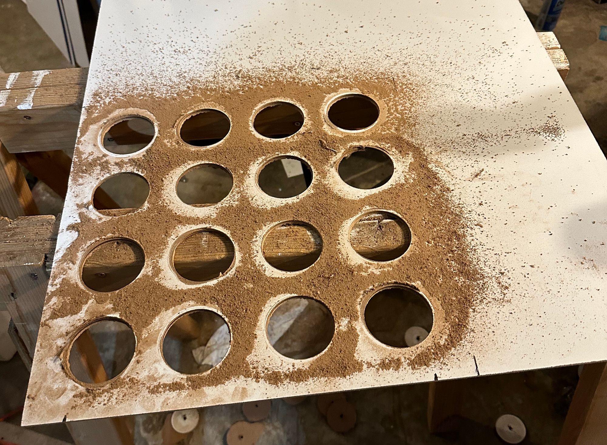
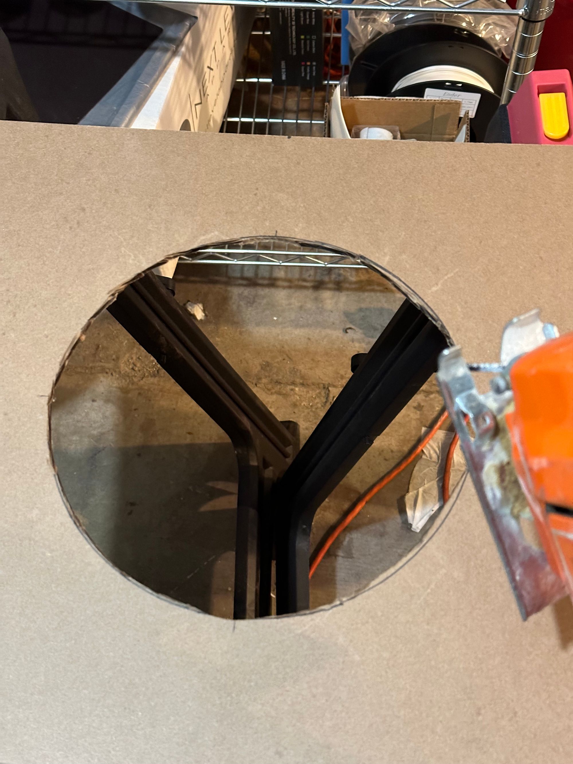
Now to clean up the rough hole I made last time, this time using an old hand-me-down jigsaw that my dad gave me over the holidays.
Alright, back to modeling the hood.
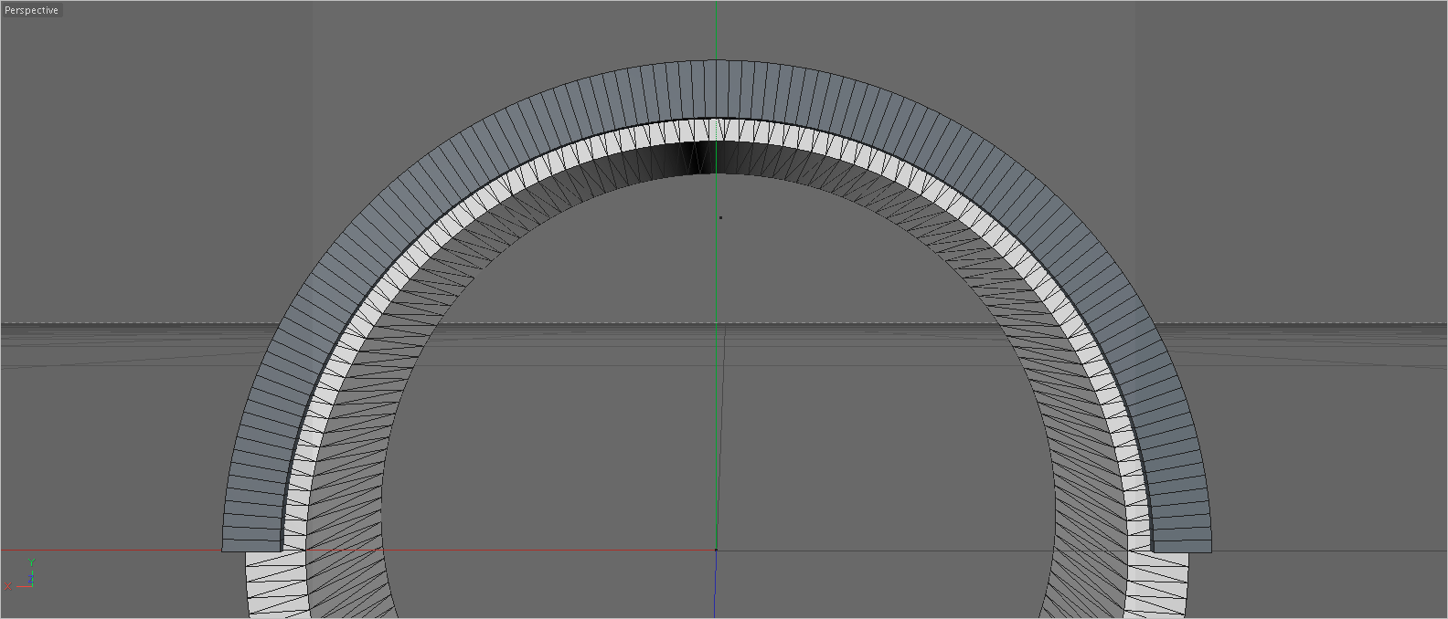
I loaded the .obj of the duct ring into C4D and started modeling around it. I was able to work out the unit conversion to know how big certain dimensions would be—I had a cheap caliper on-hand for the modeling of both pieces to help me judge thicknesses—but a lot of the work was just based on modeling in relationship to the duct ring. I started from a “tube” primitive, spanning 180° and matching the size and subdivision level I wanted.
I then constructed a simple hood structure with splines and a loft, connected the pieces, and used a “bool” object to cut a slot for the ring using the very same model of the duct ring.
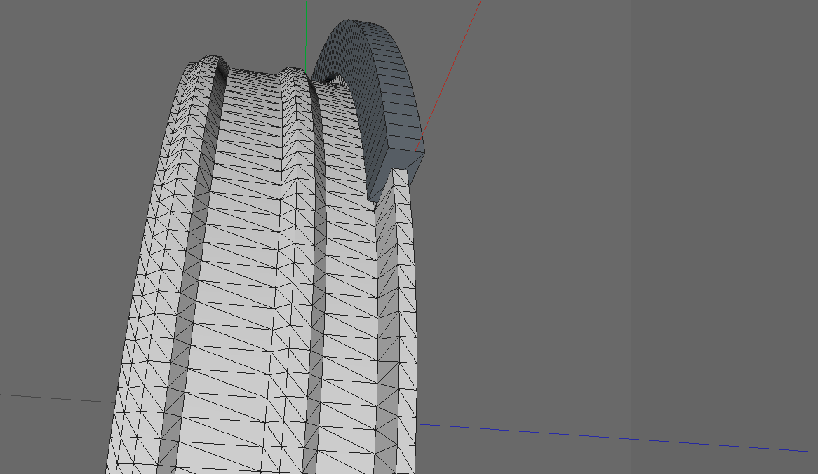
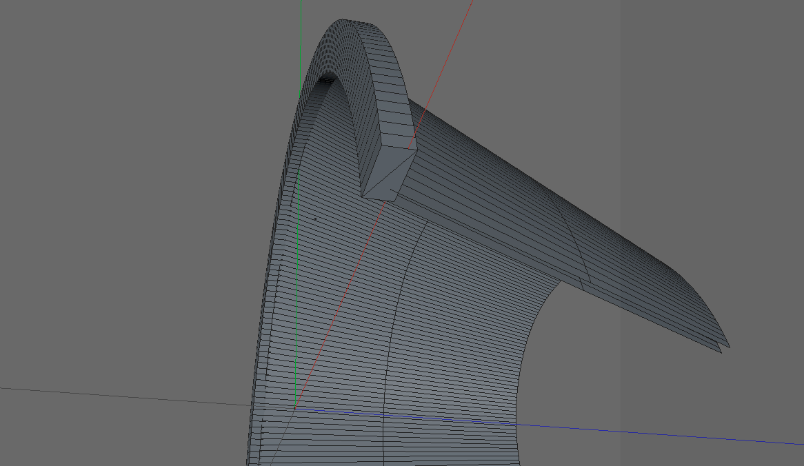
After preparing this top section, I cut the model in half so that it would fit on the print bed, then extruded the bottom edge straight down so it would slide straight on and protect against angled rainfall.
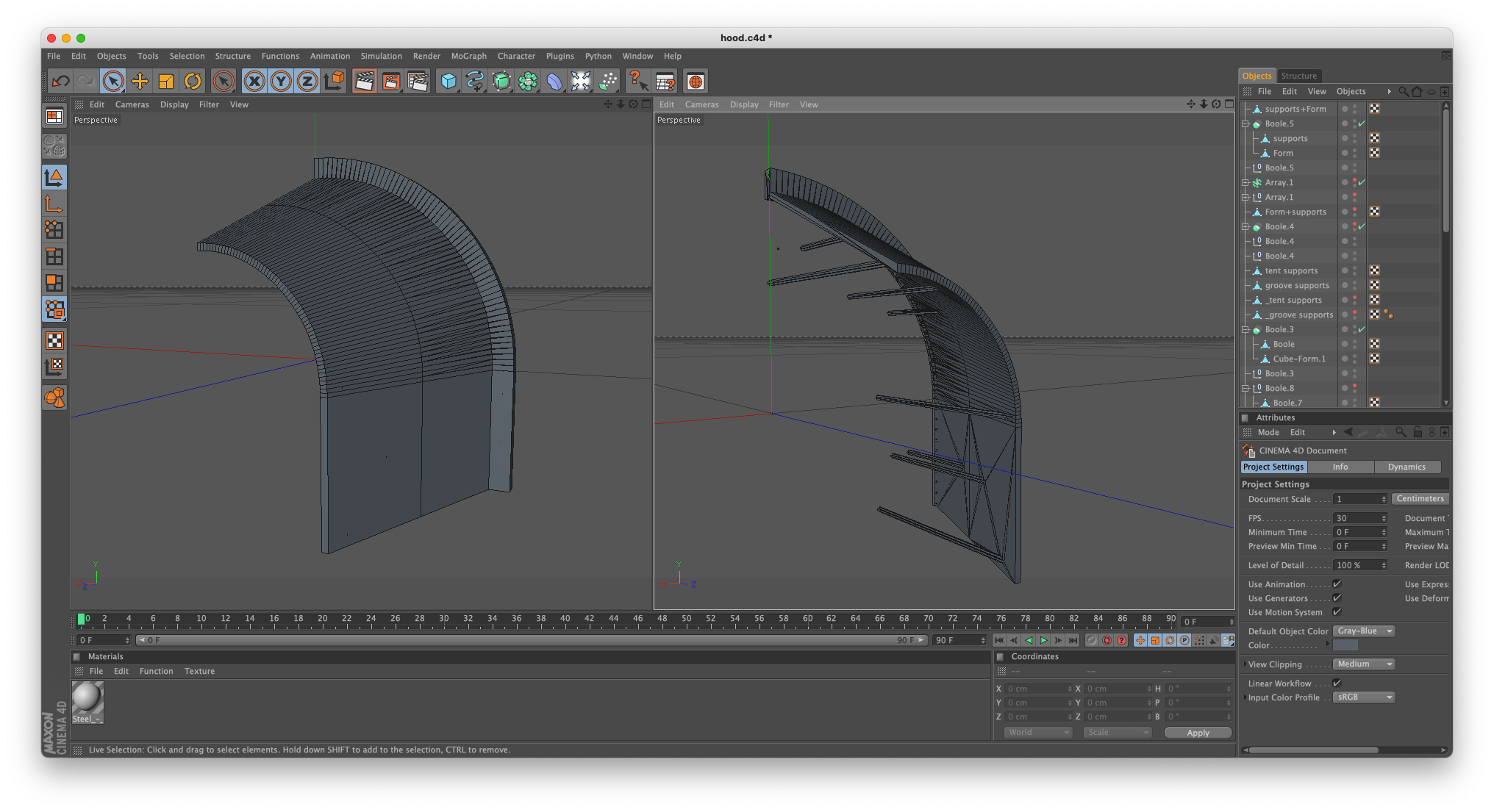
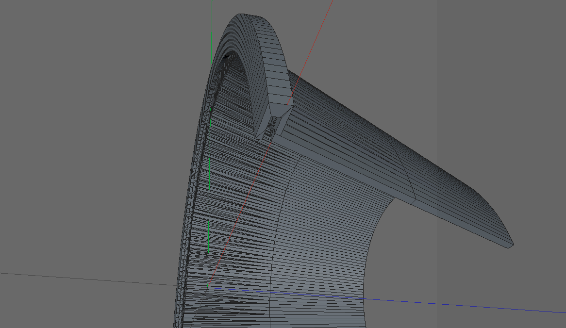
I intentionally chose an angle for the hood that could be printed unsupported, but I was still a little bit concerned about the strain it might put on the adhesion surface during printing, and it did seem important to lightly support the slot. Rather than generating supports with Cura, I chose to model my own minimal supports that I could cut out later.
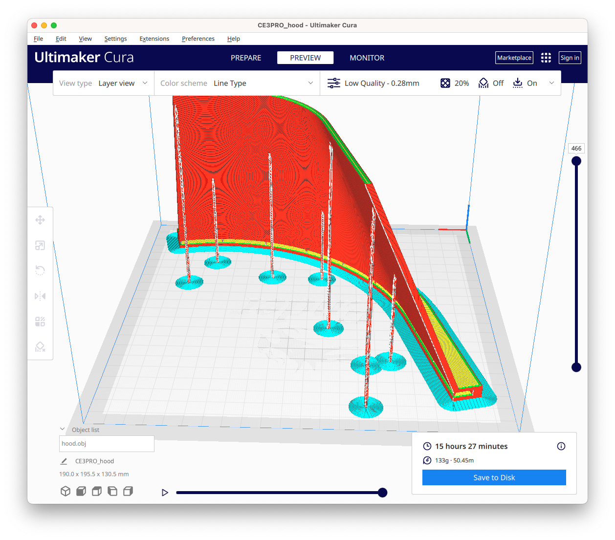
Having gotten my settings dialed in, the print went smoothly, despite being a pretty long one—over 15 hours per piece, even at low quality (for speed).
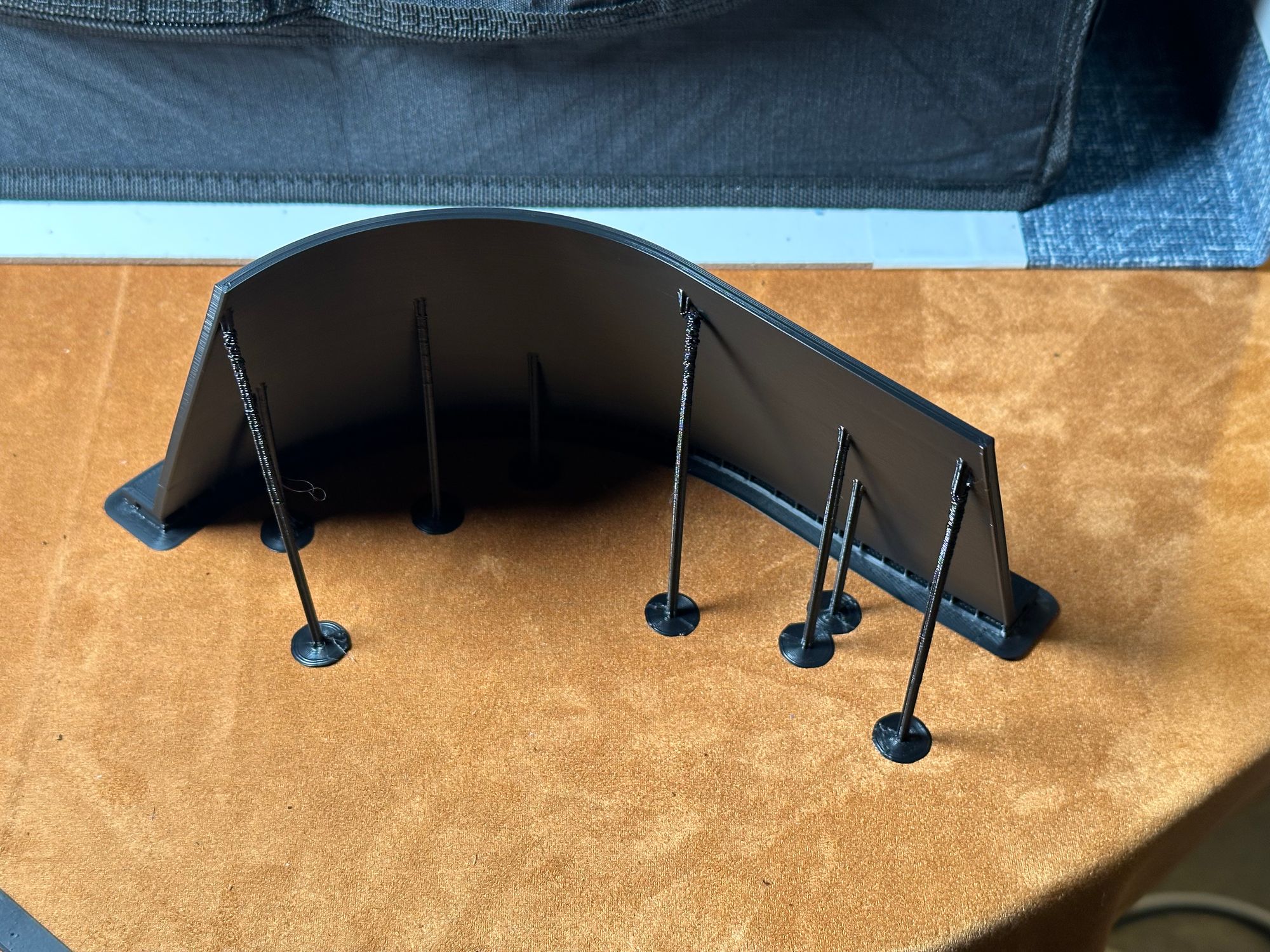
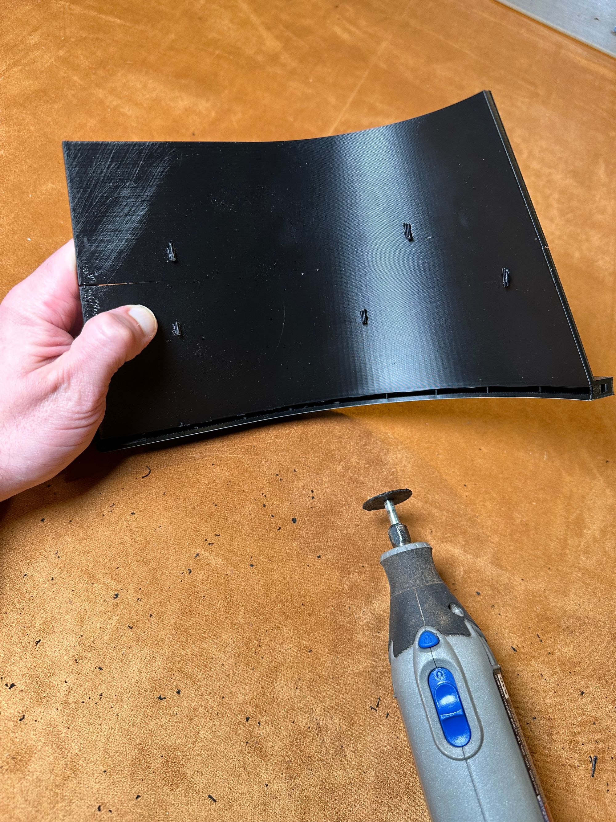
The vertical hood supports snapped off quite easily; I don’t know if they actually provided any strain relief, but nothing went wrong here so I chose not to jinx it. I started trimming the supports from the slot using a pair of nippers. Unfortunately, the stress on the piece from the nippers started creating small splits in the piece—the low quality setting seems a bit more prone to splitting. I switched to my Dremel to cut the supports instead.
After trimming the supports out, I did a test fit of this half onto the duct ring... and the already-cracked piece started to split completely. Reflecting on it, I didn’t actually leave myself any tolerance when I modeled the slot in C4D, and with thermal expansion from printing, there’s no way it was going to fit.
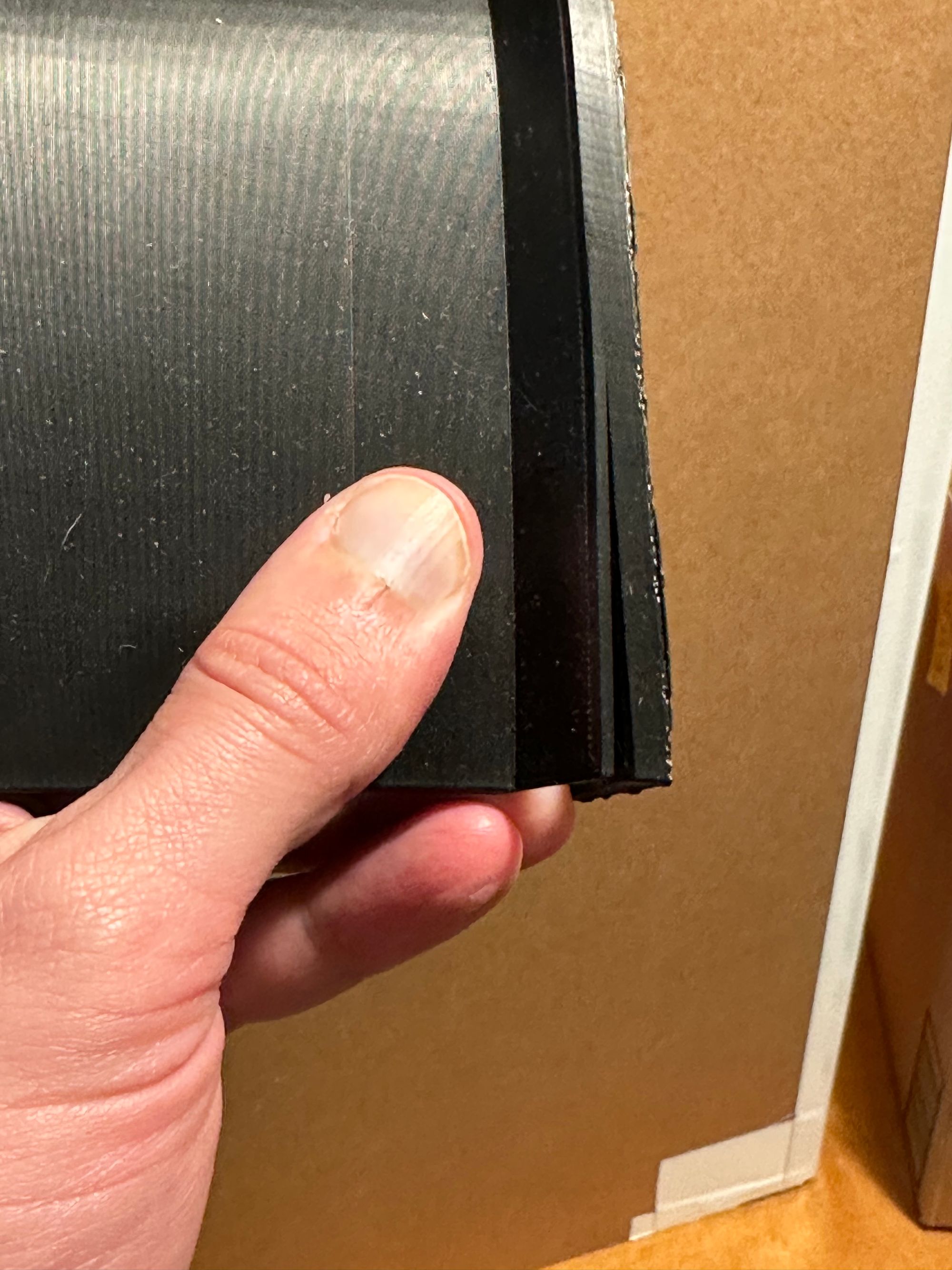
So, back to Cinema4D, rinse & repeat. Pretty straightforward to enlarge the slot a bit, then print again.
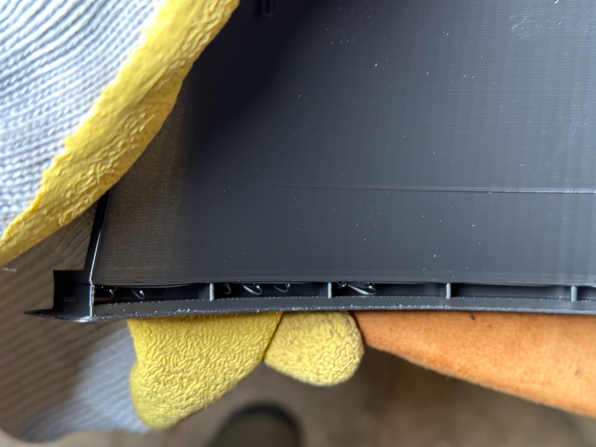
My slot supports were perhaps a little too minimal, so there were some strands of drooping material, but aesthetics aren’t important here. Just more to trim with the Dremel.
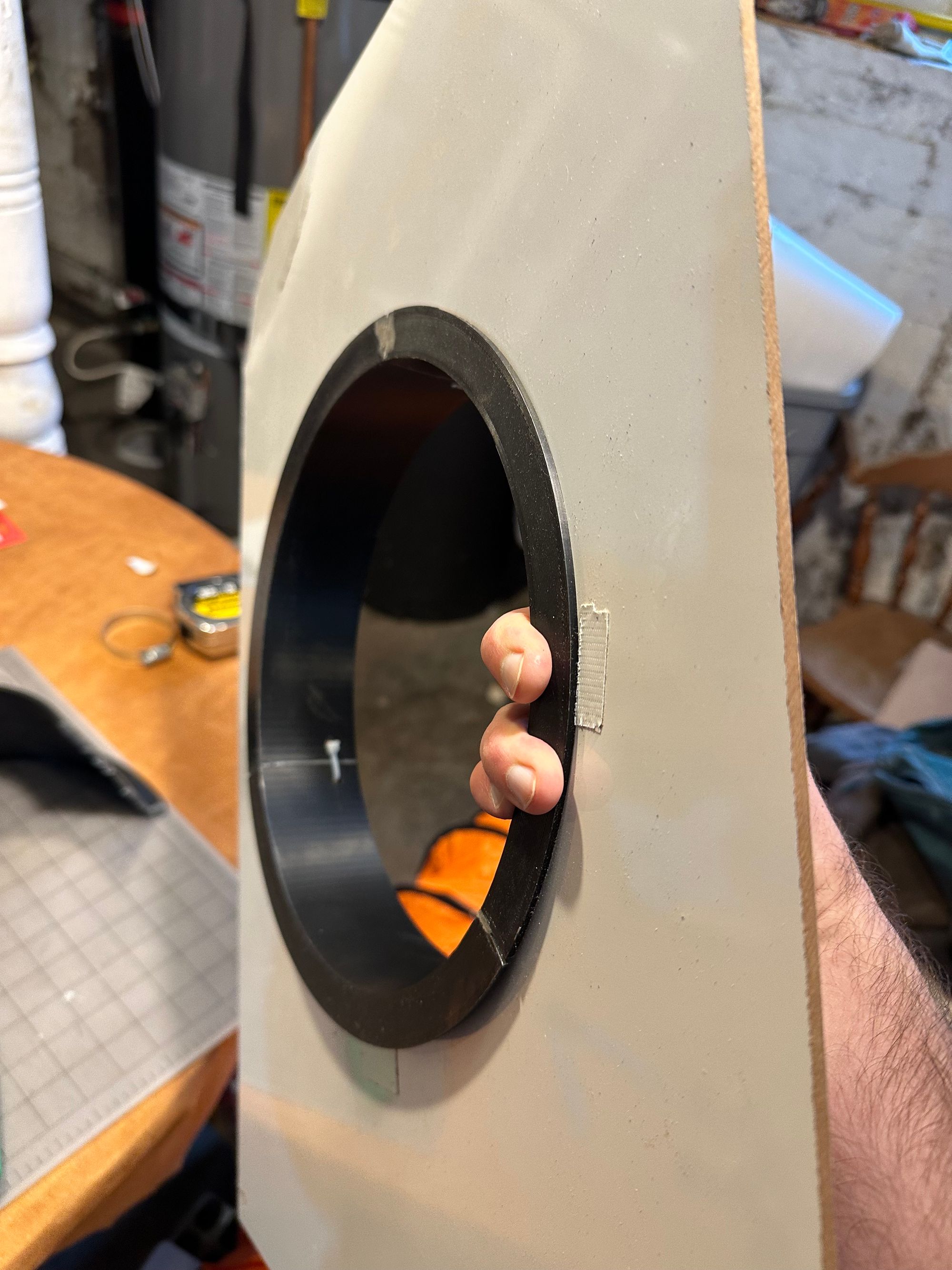
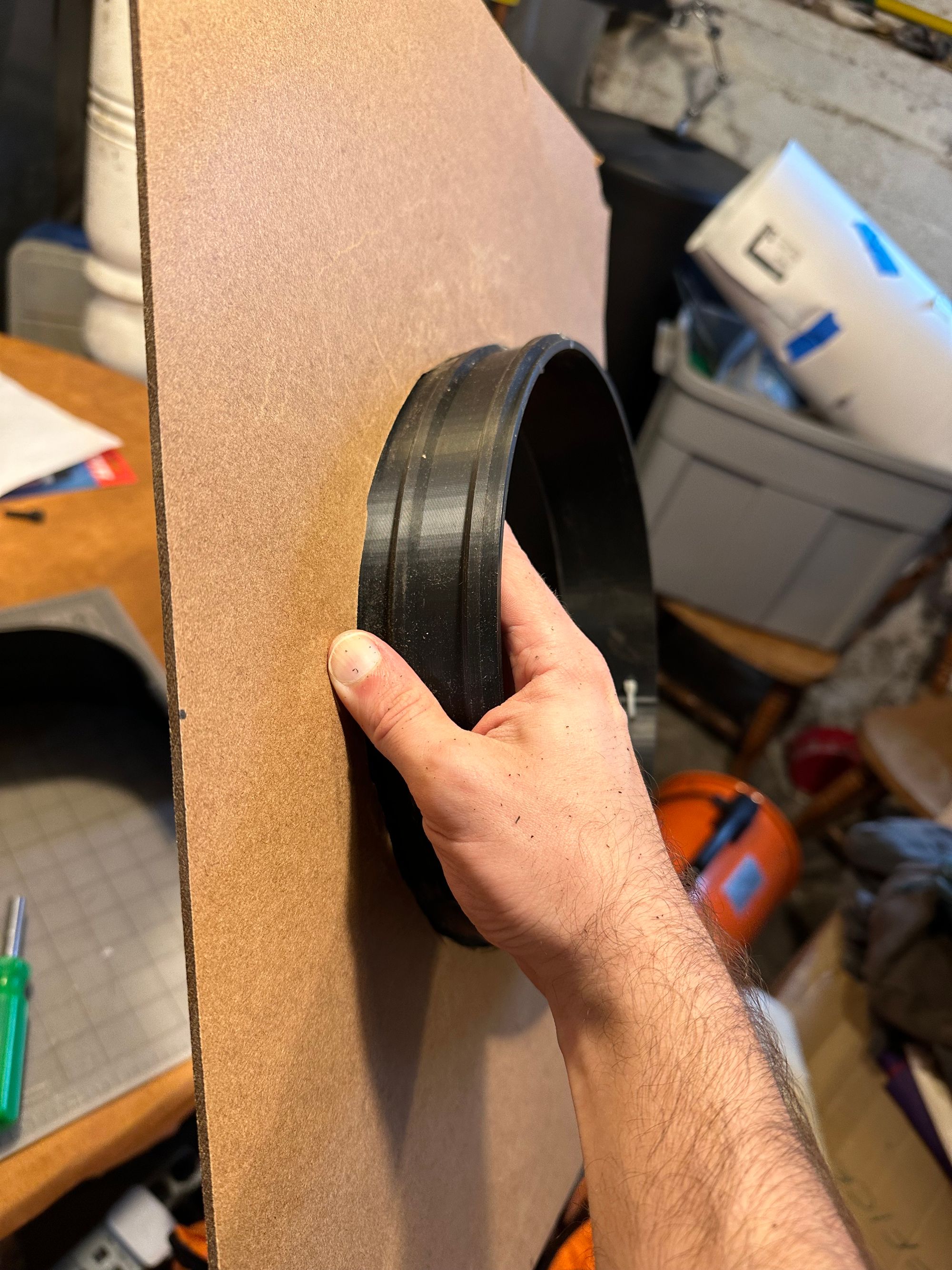
And would you look at that! It fits!
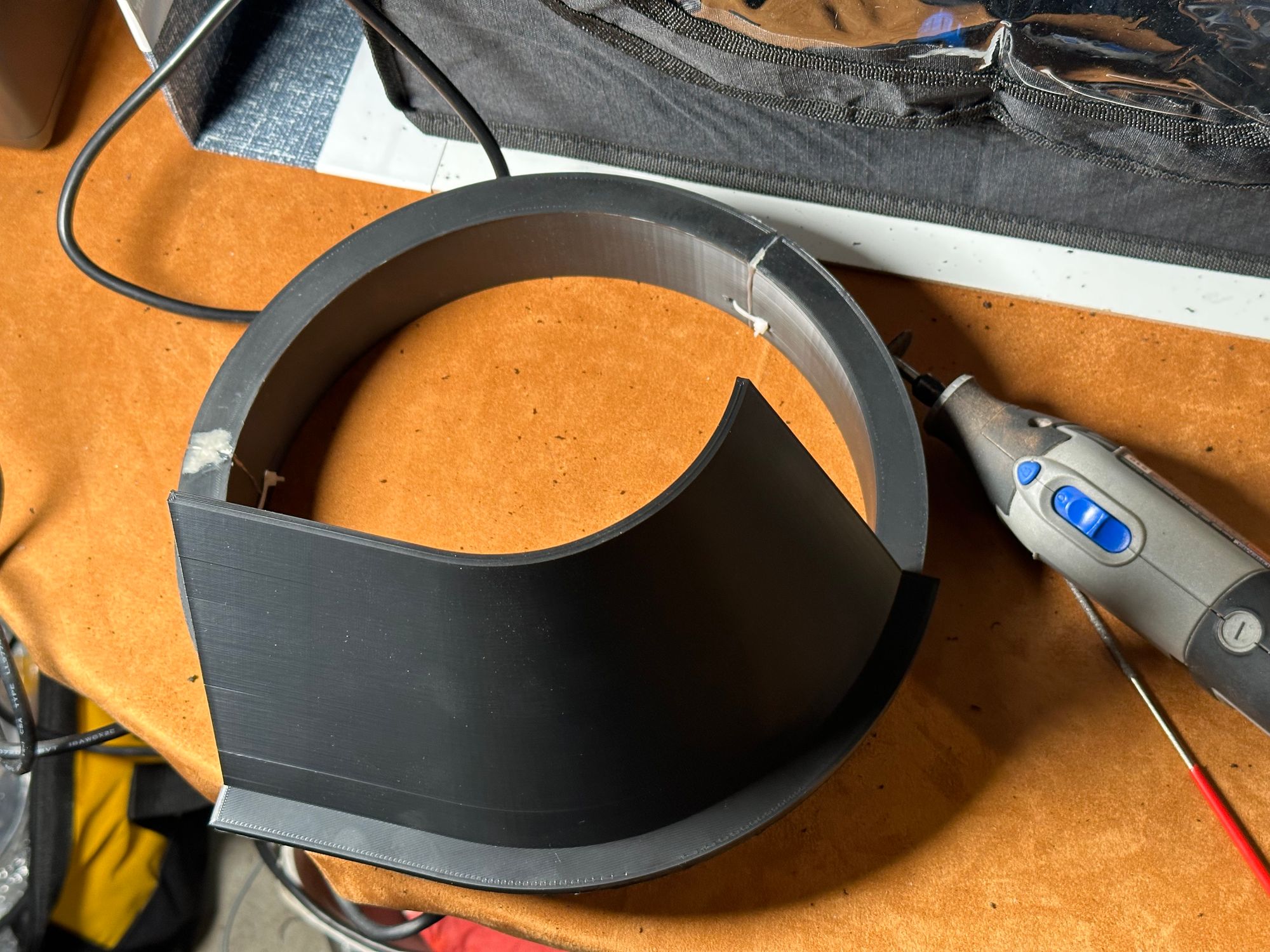
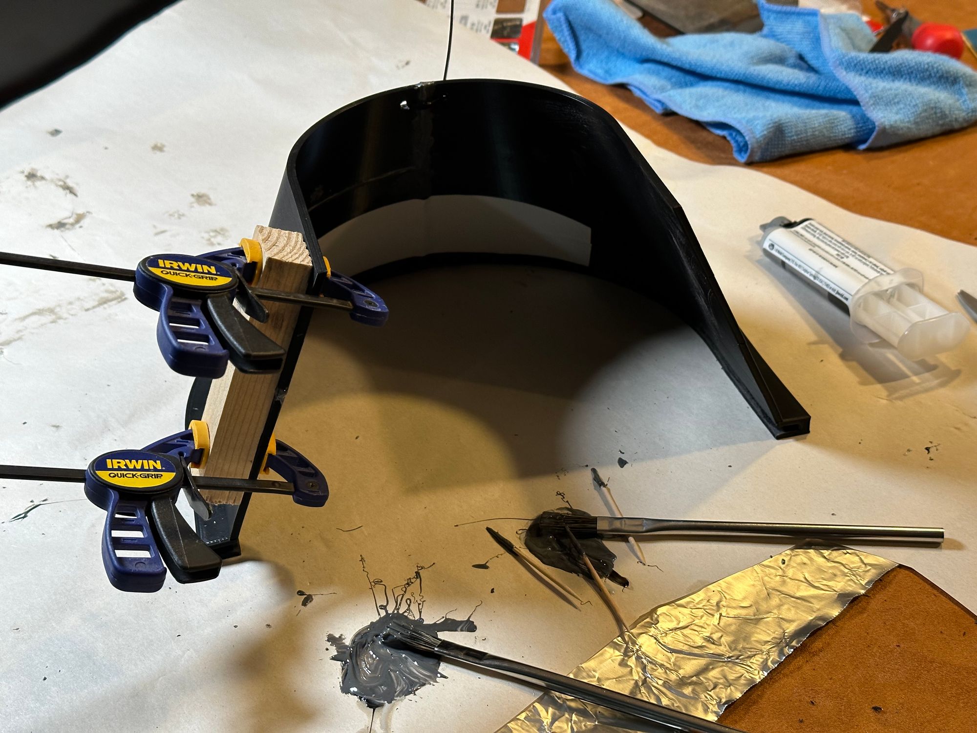
With that success, time to print the other half, trim it up, and epoxy it together.
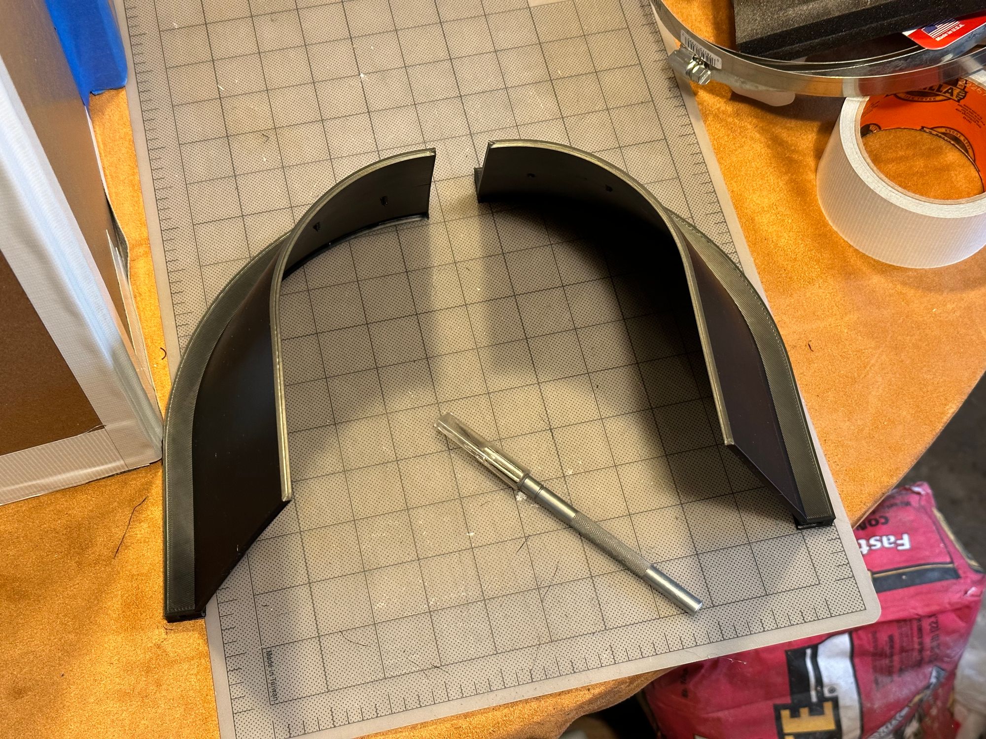
Once the epoxy had cured, I fit it onto the duct ring... and the epoxied seam cracked apart. In the end, I used the Dremel to clean up the slot a bit more, applied more epoxy (including to a split that opened up on one half of the hood), and reinforced with both zip ties and some Gorilla tape on the inside. Not winning any style points, but totally functional.
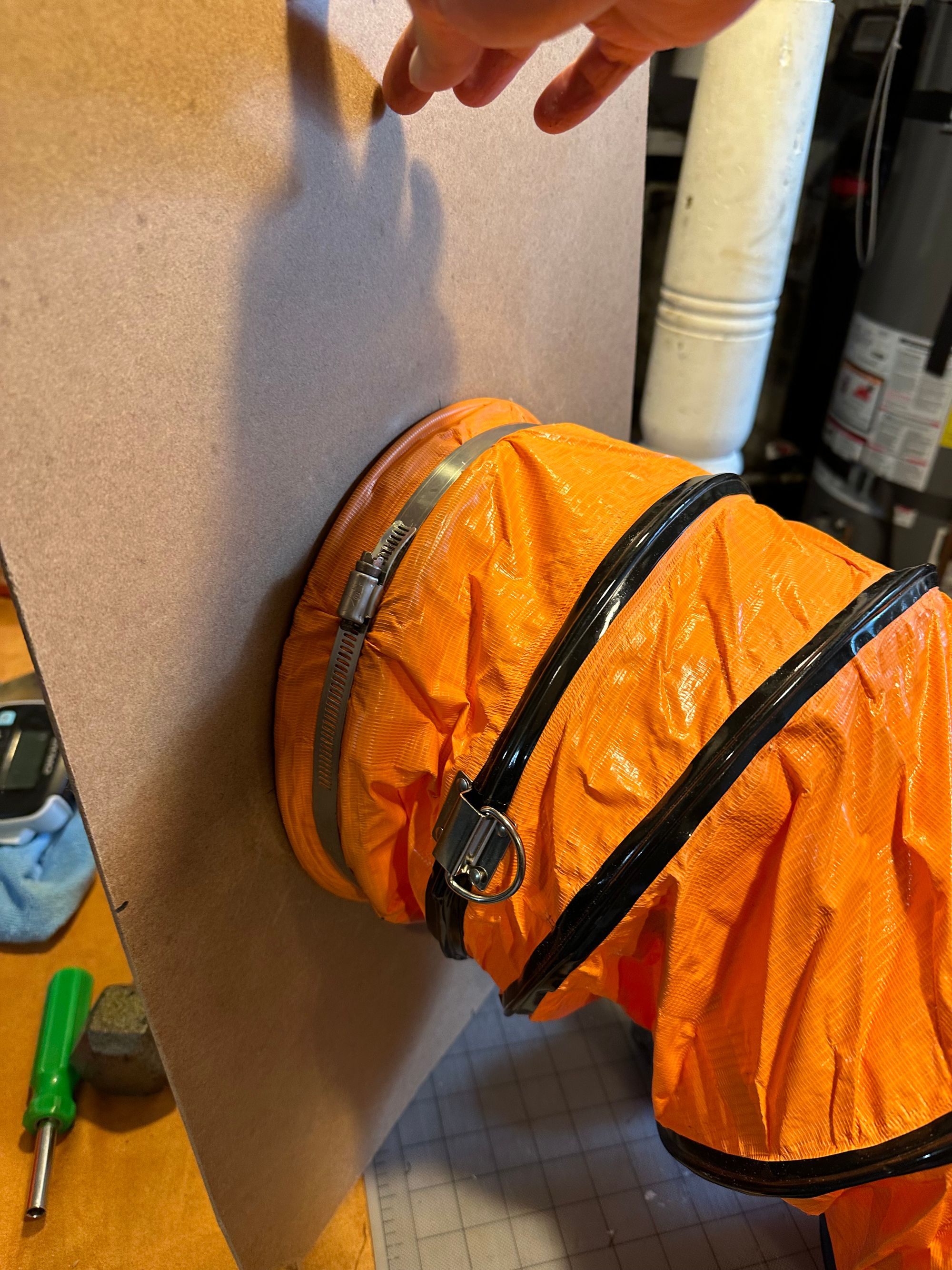
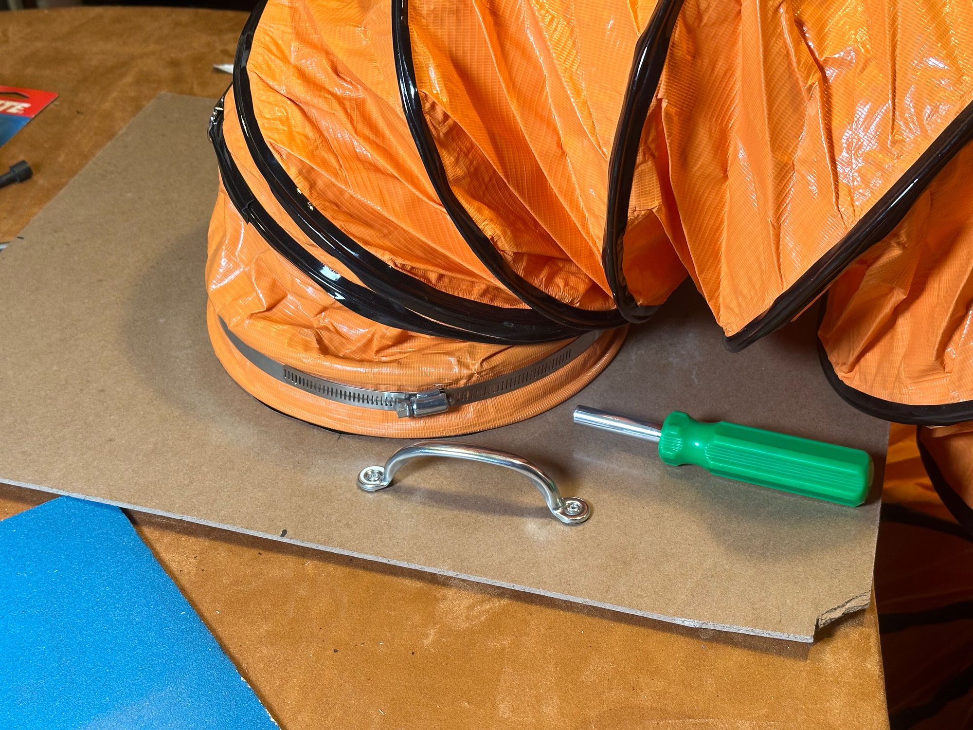
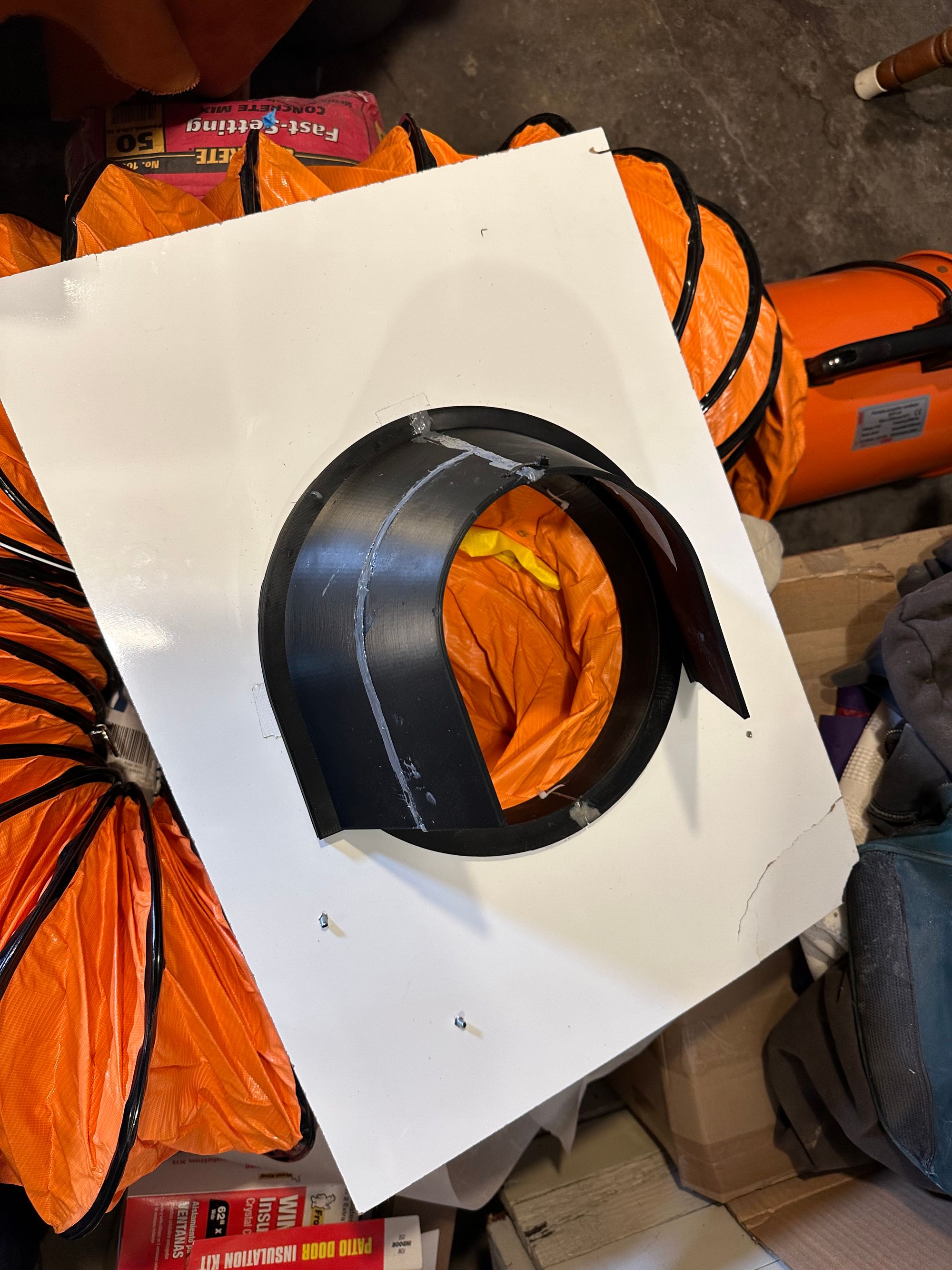
Then it was time to put it all together. A hose clamp seemed like the best way to connect the hose to the duct ring. I don’t have any single hose clamps big enough, so I just connected a few smaller ones together—like zip ties, they are very easy to chain together.
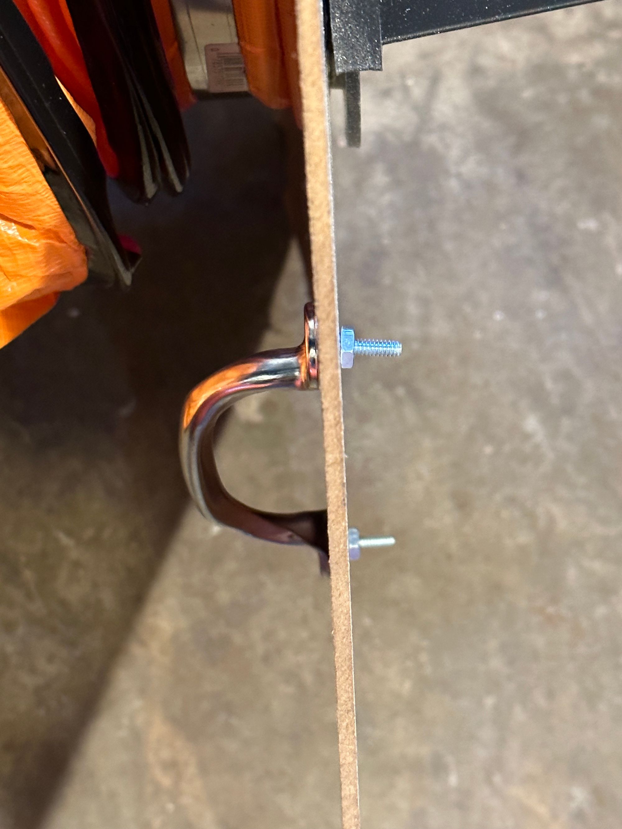
I had also been finding it tricky to get the whole piece in and out of the window, so I picked up some handles for it. I drilled holes and used pop rivets to attach them to the board, and then slid the hood into place.
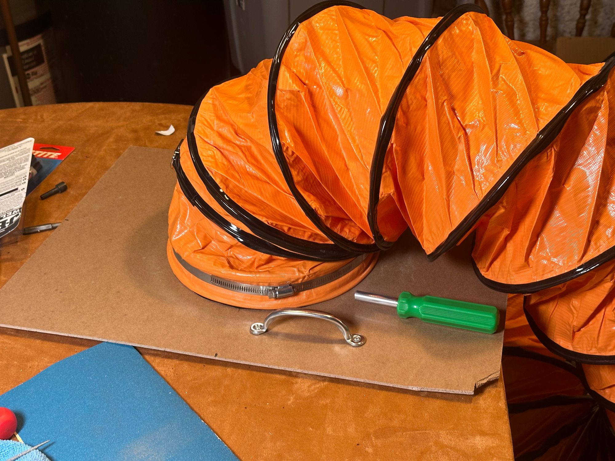
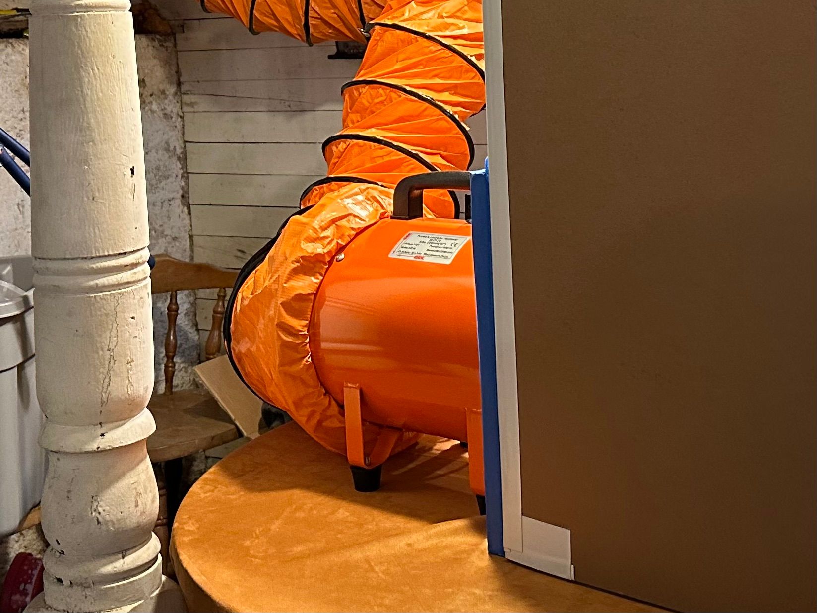
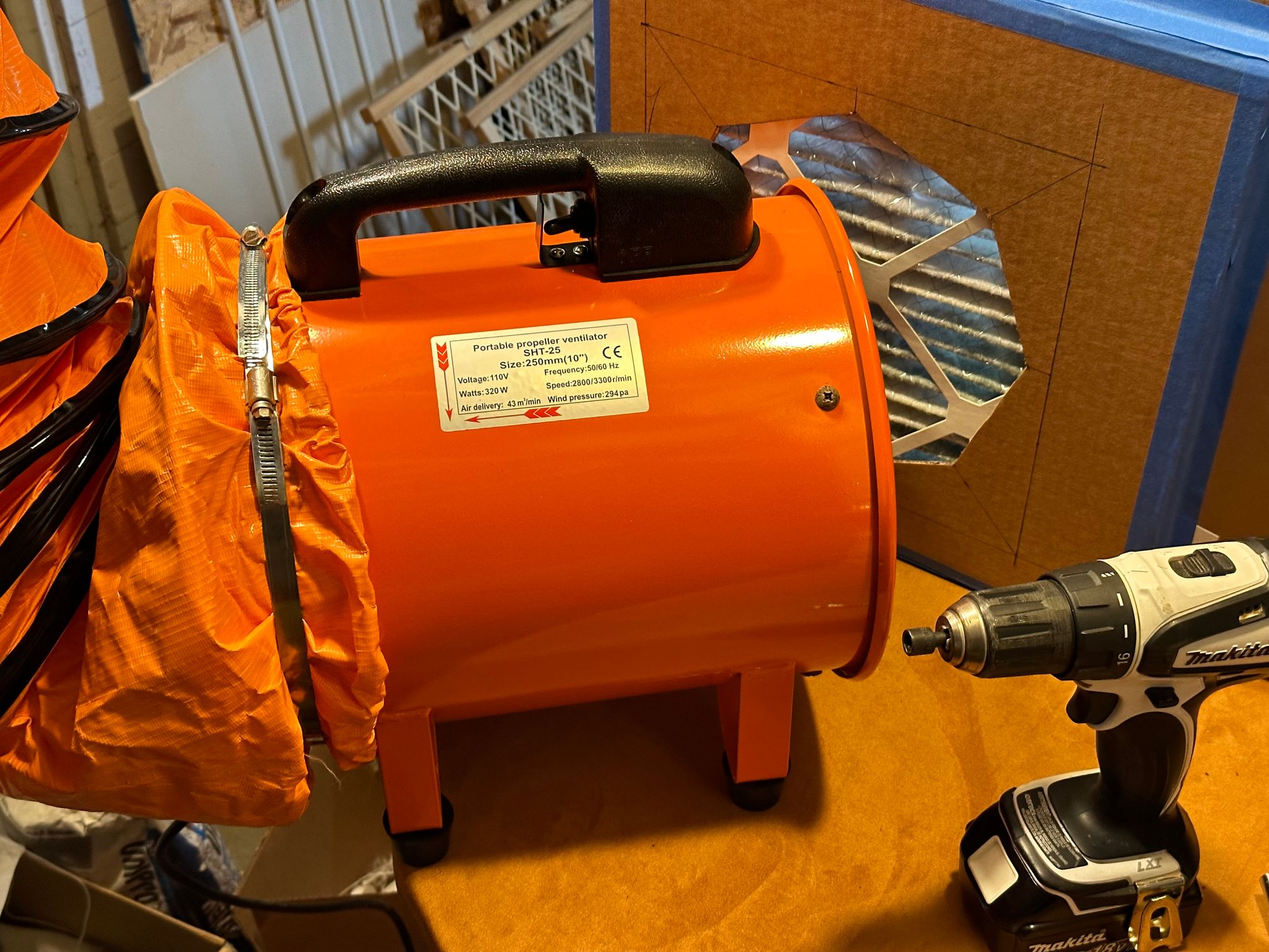
I finally tested it out, and was incredibly underwhelmed by the amount of air coming out of the vent. I discovered that a significant amount of air was actually leaking out between the blower and the hose—the hose had a built-in drawstring that I’d used to connect it to the blower, but it was woefully insufficient at maintaining a decent seal. Leaking all that air back into the workshop defeats the purpose of the venting system—I needed to actually move all that air out.
More hose clamps!
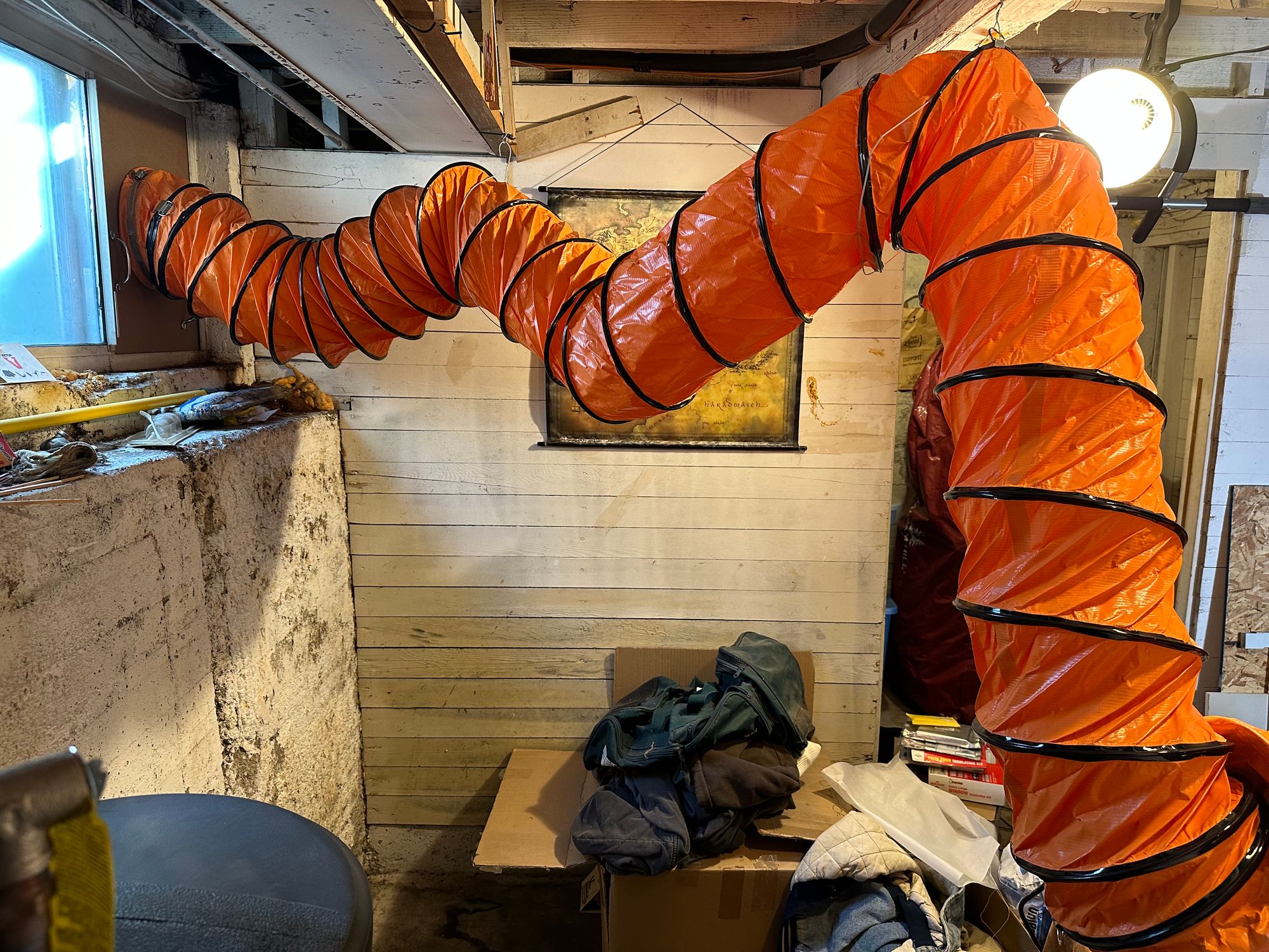
I also used a few cup hooks and old metal clothes hangers that I had lying around to better hang the hose, minimizing sharp bends on the way to the window. I bent the clothes hangers to fit and passed them through smaller rings on the duct hose, making itvery easy to attach to the hooks when setting up and then detach when I'm finished.
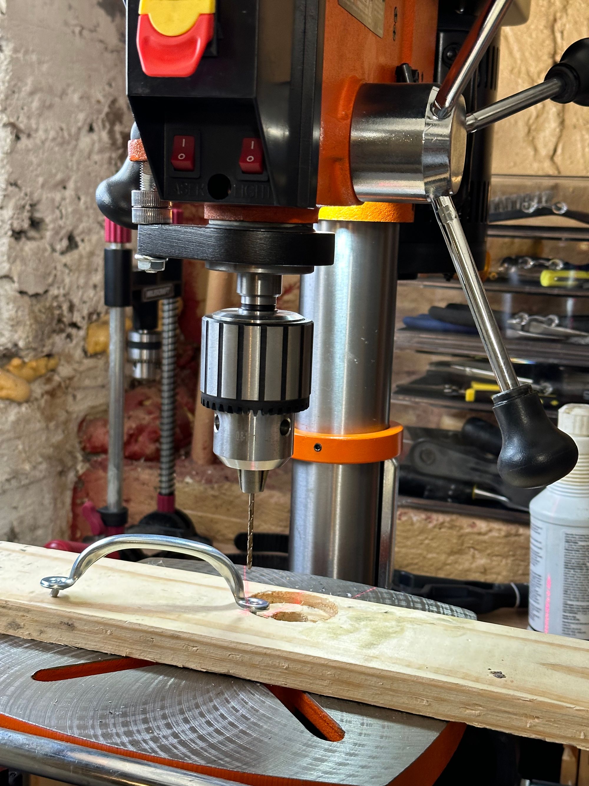
Finally, the rivets didn’t actually open up terribly well, and one pulled out after a bit of handling. So I forced the rest of the rivets back through the board, drilled them out of the handle with the drill press, and then reattached the handles with machine screws and nuts, which is feeling much more secure.
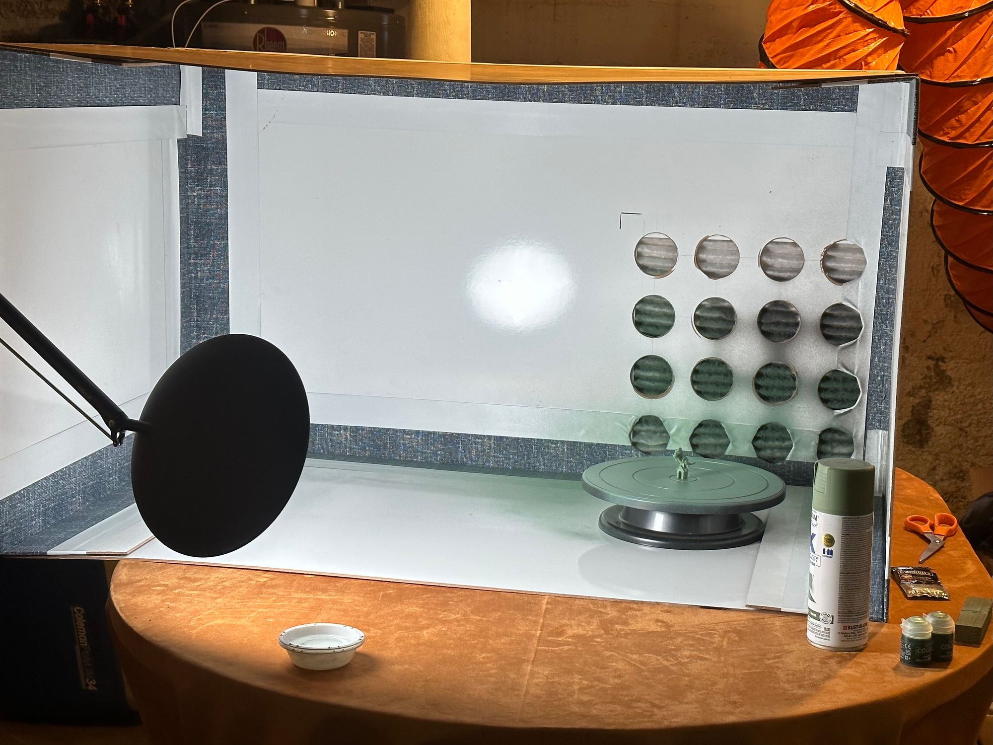
After all those ups-and-downs, it works! Getting really great airflow now, drawing air from the paint booth and moving it effectively outside into the window well.
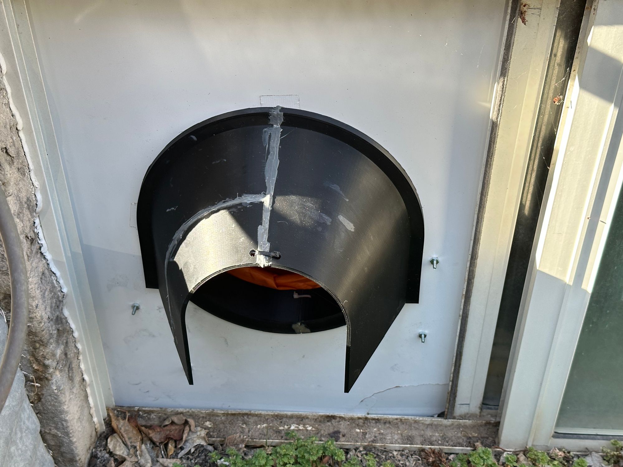
All in all, it was a much bigger and more involved process than I expected at the outset. Despite the aesthetic crunchiness, I am thrilled with how it turned out. I’ve now got a reliable, sturdy venting system, which is quick and easy for me to set up and take down, and moves air very nicely. After all this work, it was great to get into some painting. But that will be another post!